OK, another weekend, another subsystem. This time I've been working on a prototype for my tracks module.
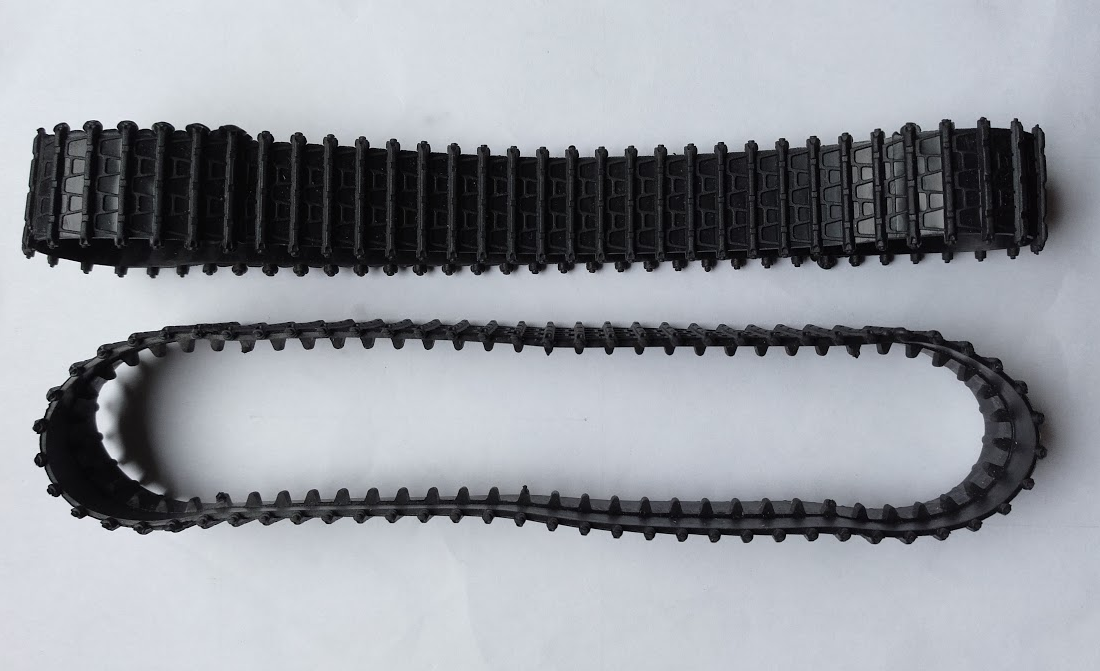
The robot will be tracked (tank, caterpillar whatever) - I bought some rubber tank tracks from Aliexpress (type D), and assumed I would sort out my own pulleys either lasering, 3D printing or milling them.
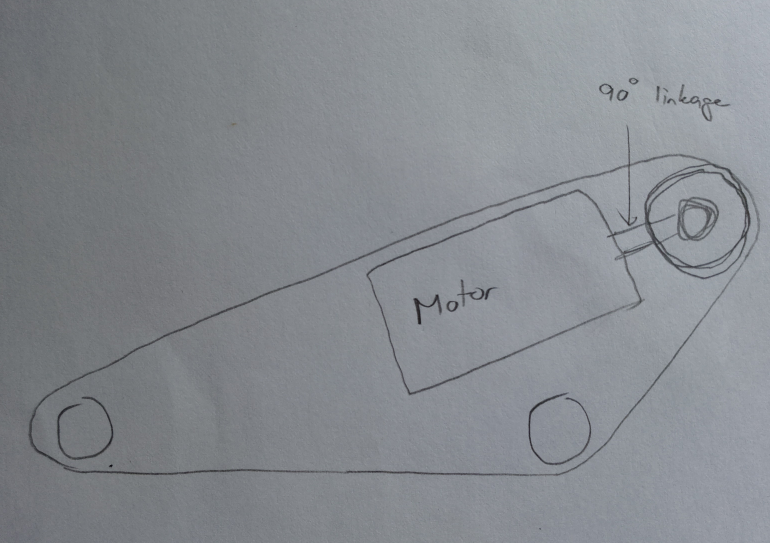
I originally wanted to put the motor inside the circumference of the track - aligned parallel with the direction of travel - and then have a 90° linkage to transfer the motion to the pulleys. This would save space inside the fairly cramped robot, and also give a nicely centralised, very low centre of gravity:
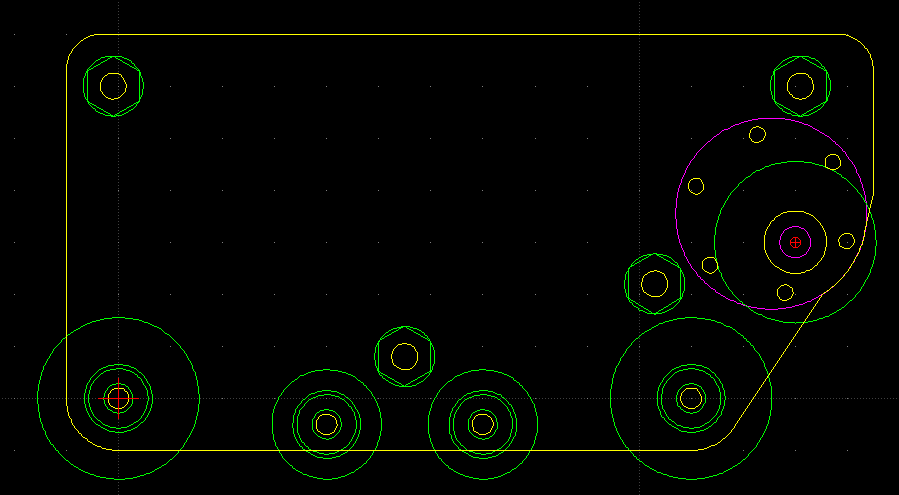
Unfortunately, the tracks are too short to give me space for the motors, and so instead I've had to opt for pretty much the opposite - the motors will be directly connected to the drive pulley, at perpendicular to the direction of travel - and will be pretty high up! (Magenta is the motor in this image):
Pulleys
The first challenge was to reverse-engineer a pulley by measuring the track. The tracks didn't come with any kind of engineering drawing or measurements, so I had to wing it by hand. One significant challenge is that the rubber obviously moves when you try to measure it... any pressure from a caliper squashes the rubber and your reading is no good.
The tracks have a row of teeth along the centre, which ideally I want to drive. They also have castellations along the outside edges which we could also use for drive.
My big fear is throwing a track, so I really want as much registration as possible to avoid the track falling off. The secondary concern is to avoid slippage on the wheels so that my motor encoders can be at least some use for dead-reckoning tracking.
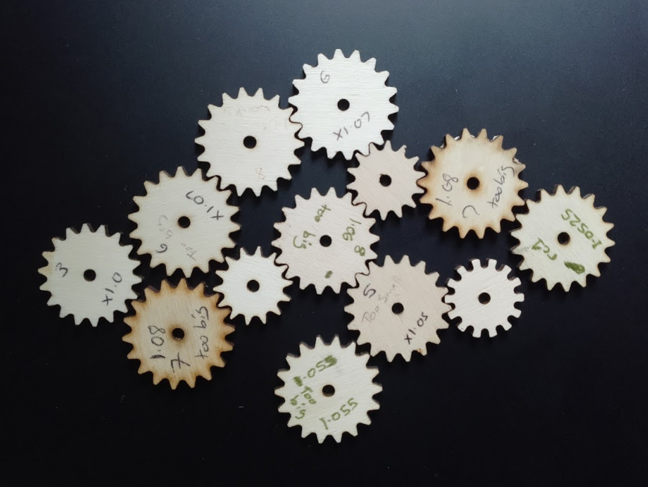
And so began a highly iterative process to try and derive the right dimensions for my pulley. It took me about 10 iterations on the laser cutter to find something that ran "well enough" - you'll see one gear below which has a different tooth profile - that just has the track tooth profile cut out of it - but of course the teeth bind horribly as they're wrapped around the wheel. That was the first attempt, and was rectified in the later designs.
I started with a fully laser-cut prototype, with no motor, no bearings - just layers of laser-cut wood mounted on bamboo skewers. I don't have any photos of it, but it gave me confidence that my pulley design was close enough, and that the overall size of the track was appropriate for the length of the rubber. (I don't have any photos from that... sorry).
Lasering was a quick way to iterate prototypes, but I decided to 3D print the pulleys for the "final" prototype.
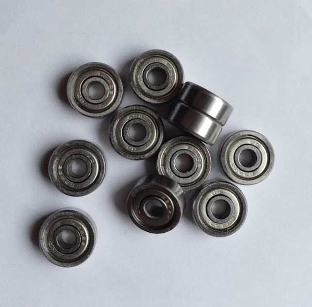
I got some small bearings from China on ebay. They're fine - except that they came lubricated with what appears to be thick treacle - honestly the bearings as delivered would barely turn. I had to guy and buy some acetone nail varnish remover (which cost more than the 30 bearings!), and clean them up. Now, they're pretty good.
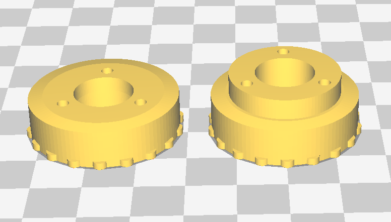
I drew up a pulley design in OpenSCAD, in two flavours - one without teeth for the idler wheels, and one with teeth and a hole for designed for the motor shaft for the drive pulley.
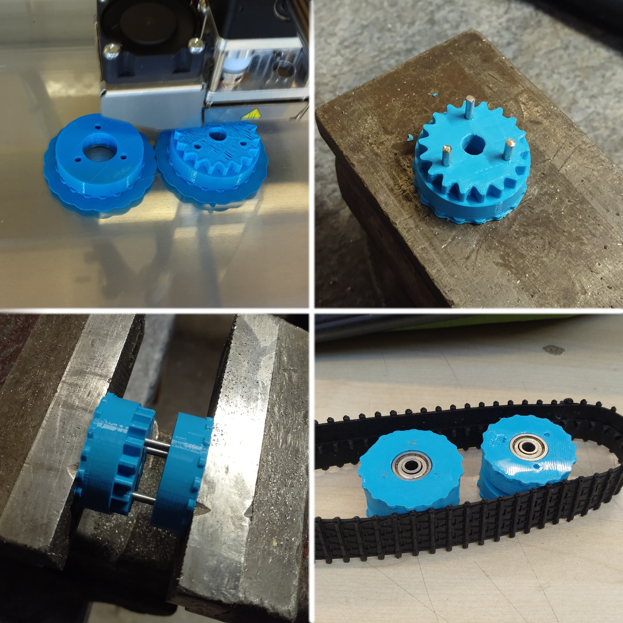
So I printed two idlers, and one drive pully - slightly tweaking the design after each one (drive wheel was last - as it has the important drive teeth and so needed to be the most accurate).
To avoid any overhangs, I print the wheels in two halves, and then connect the two together with some coathanger wire. The result is actually very secure, and the bearings sit in my bearing cups very nicely:
Mounting and Structure
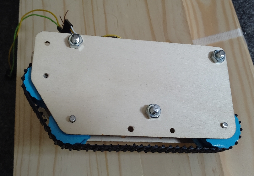
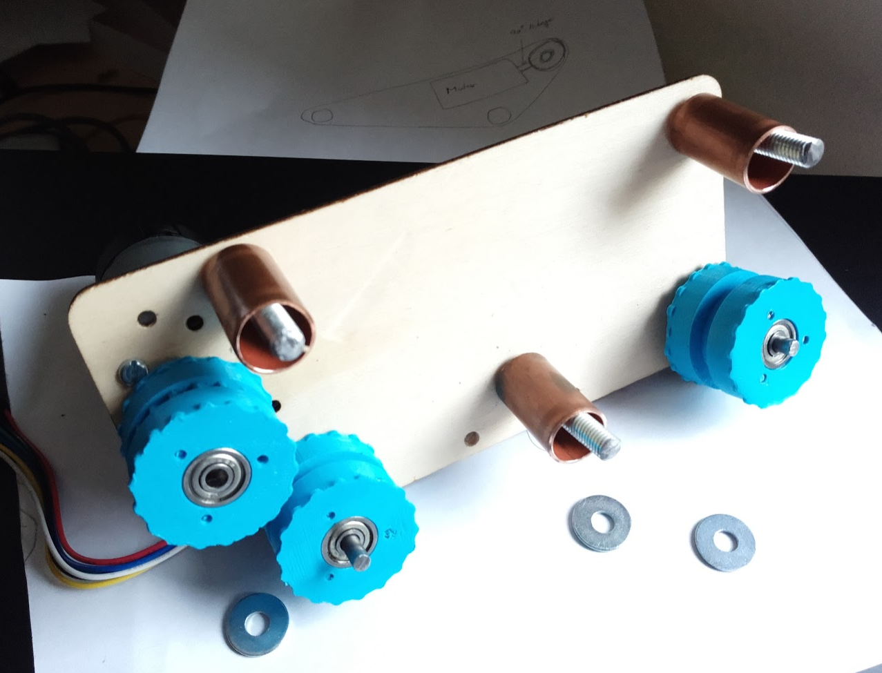
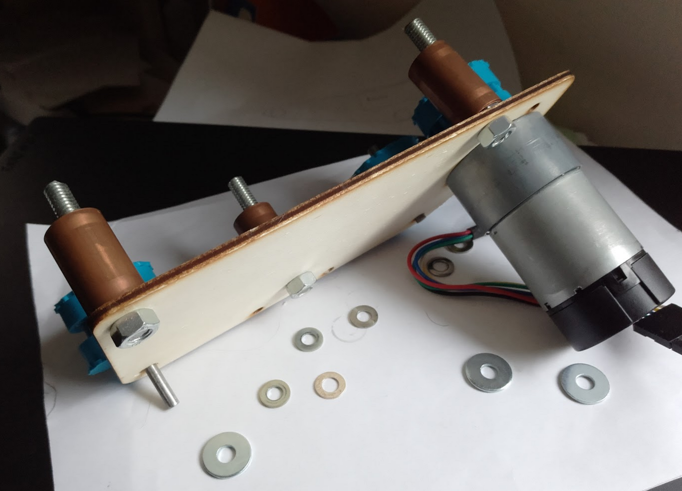
With pulleys done, I modified my plywood prototype to support the 4 mm rods (for the bearings) instead of 3 mm bamboo skewers, and to support some threaded-rod spacers. My M3 Nylon spacers are on a slow boat from China, so I've improvised using some copper pipe which I had to hand, which I've cut to the same 25mm that my spacers will be.
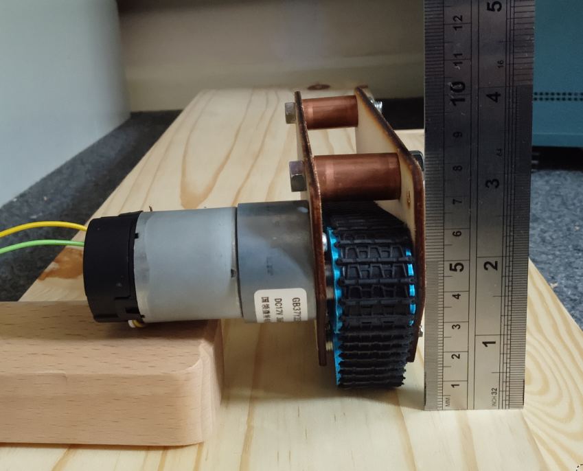
Finally, with the prototype constructed I could try plugging it in... and it works better than expected!
Running at 5V (final robot will be 3S 11.1V battery), the motor has really good torque. The tracks don't slip at all (at least at this voltage the motor stalls before they do). Also the exposed track at the front, and the very forward centre of gravity makes it really good at climbing obstacles.
Next Steps
Now I need to make a new pair of modules, with the final pulley design and properly designed side pieces (instead of ones that I hacked up a few times) - and probably I'll wait for my nylon spacers to do that so I can do away with the copper pipe.
Discussions
Become a Hackaday.io Member
Create an account to leave a comment. Already have an account? Log In.