OK, so the reason this robot is called Bot Matrix, is because one of the central components is a 32x32 RGB LED matrix.
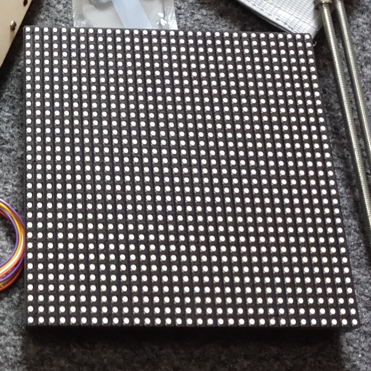
These LED panels are the type used in Jumbotron screens or advertising billboards. They have a set of shift-registers and constant current drivers on-board, and use a somewhat standard interface which seems to be called HUB75.
Sourcing the Panel
HUB75 panels aren't too hard to find - though I did have a certain amount of trouble getting a 5mm-pitch, 32x32 pixel panel.
Pimoroni sell P4 and P6 (4mm/6mm pitch): https://shop.pimoroni.com/products/rgb-led-matrix-panel
Adafruit have a selection, but their 32x32 P5 is $45 USD! (Plus shipping from the US), which was too much for me: https://www.adafruit.com/category/327
I went shopping on Aliexpress, and found plenty for around $20-$30 USD, delivered to the UK: https://www.aliexpress.com/wholesale?catId=0&initiative_id=SB_20171022045534&isPremium=y&SearchText=P5+rgb+matrix
Driving the Panel
The panels themselves are not able to display an image - they must be continually scanned with data, and if PWM is desired/required, then that needs to be provided in the input too. This means they have pretty hefty driver requirements - and in commercial setups they seem to often use FPGAs to generate the control signals.
Hackaday previously featured this project by Frans-Willem which drives a set of HUB75 panels from an STM32F407 - and I just so happened to have bought an STM32F407 for something else, so I set to trying to use that code to drive my panel.
I'll forgo a detailed description of how the drive signals work - Frans-Willem already did a great job explaining it in his writeup.
Basically, there's a set of pins which choose which row of the panel to activate, a set of pins connected to the shift registers to shift data in to that row, and a set of pins to latch and display that line.
You have to scan through each line, latching in and displaying data for that line before moving on to the next.
If you want full colour (not just 3-bit colour) you also need PWM. Frans-Willem came up with an elegant solution whereby the appropriate bit-patterns to give PWM-ed colours is stored in memory, then directly written to the STM32's output pins using DMA - this puts full-color, 60 FPS refresh rate on a 32x32 panel within reach of an STM32F4!
The quirks of my specific panel
The seller I bought my panel from claimed it was 1/16th scan - this means that the rows are scanned in groups of 16 rows, with two busses. This eventually turned out not to be the case - it took me a long time to figure out what was wrong, as there was another issue causing strange output.
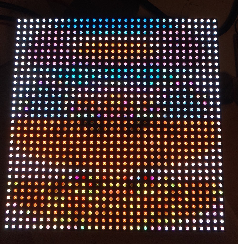
Eventually, I figured out it was in-fact 1/8th scan, as evidenced by the "D" pin being tied permanently to ground, and hidden under a sticker on the board, it indeed said "P5-32x32-8S-75-13A". So once I had changed the config to expect a 1/8th scan instead of 1/16th, I started getting output that made some sense.
There was still a problem - I was now displaying "stripes" of 8 rows of pixels, but the stripes were in the wrong order. It turns out the way the shift registers relate to the panel pixels are non-intuitive on my panel:
commit 6c1b8b84e7d8927119d1bfaf2ba36b600a05bbaa
Author: XXX
Date:   Sat Sep 9 15:57:10 2017 +0100
    Add remapping

    My panel has a strange pixel layout. Though the physical dimensions are
    32x32, logically the electronics are laid out as 1/8 scan with 64 pixels
    per row.

    If the 32x32 panel was split up as below:

     0                              31
     +---------------+---------------+ 0
     |               A               |
     |                               |
     +---------------+---------------+ 8
     |               B               |
     |                               |
     +---------------+---------------+ 16
     |               C               |
     |                               |
     +---------------+---------------+ 24
     |               D               |
     |                               |
     +---------------+---------------+

    Then the physical shift registers are arranged as 64x16, with the layout
    below:

     0                                                              63
     +---------------+---------------+---------------+---------------+ 0
     |               B               |               A               |    BUS0
     |                               |                               |
     +---------------+---------------+---------------+---------------+ 8
     |               D               |               C               |    BUS1
     |                               |                               |
     +---------------+---------------+---------------+---------------+

    To support this, add a function which is called by "framebuffer_write()"
    which adjusts the given offset to map it to the different display
    layout.
I've seen talk around the web of other panel layouts - so if you do embark on trying to drive one of these things, be aware you might need to reverse-engineer the pixel layout.
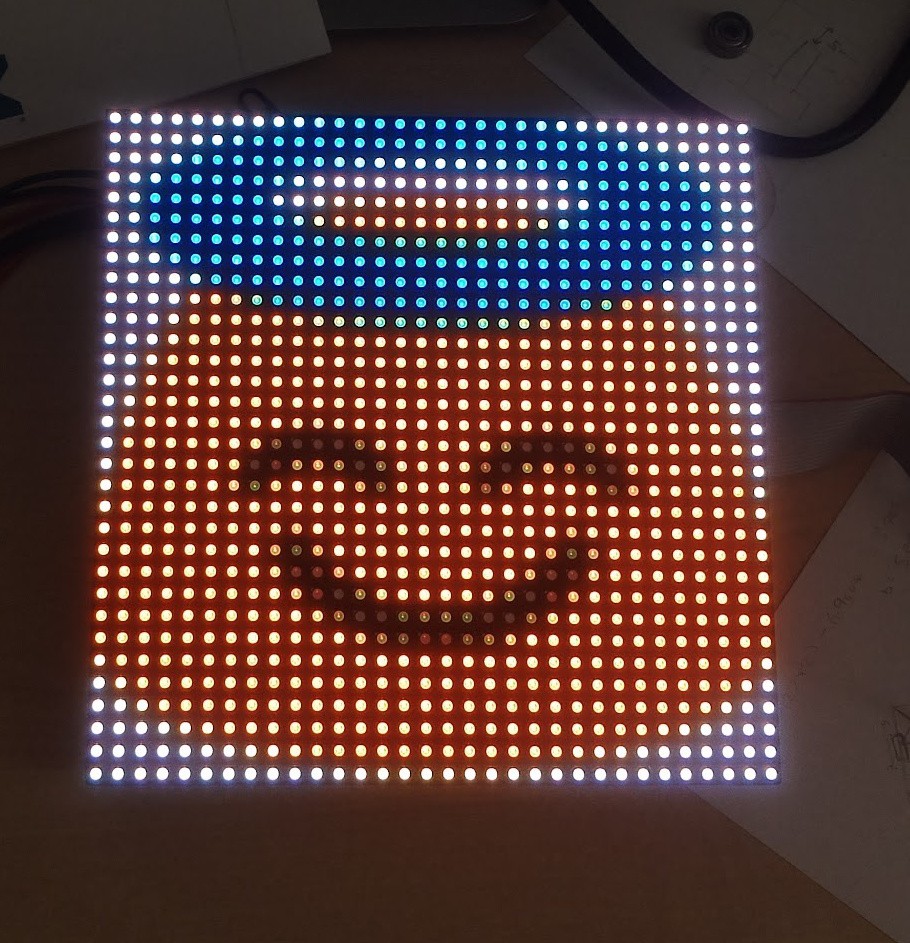
Once I'd finally figured out how the pixels are laid out, I added a routine to Frans-Willem's code to map from the "standard" pixel layout to my panel's quirky one. I wanted to do this on the microcontroller instead of the "host" (Pi or whatever), so that the host can just send raster-scan-order data.
With all that done, I could finally display an actual image! (Exported from GIMP as a C-header):
Control over SPI
I was keen to use SPI to upload my pixel data to the panel, as the Pi3 only has one "good" serial port, and that's connected to the Bluetooth chip (which I also want).
I set about adding a SPI slave implementation to receive pixel data from the SPI and write it to the framebuffer.
It took me quite a while to get the DMA state machine working reliably, but I eventually got there, and could send data from the Pi over SPI. The SPI stays stable up to around 3 MHz, and a framebuffer is about 4kB, so theoretically, the max framerate dictated by the SPI would be:
Totally adequate (but remember it's an upper limit, if the SPI runs at full speed all the time - not the case because both the Pi and the microcontroller need to do some processing).
I grabbed some Matrix code off the net and made it work on my panel - python manages to get 45 FPS in real-world performance:
I did some investigation in to where the bottle-neck was, and found that the microcontroller was spending a huge amount of time writing the framebuffer - as I mentioned at the start, the way the code works is by generating a special bit-pattern in memory representing the PWM signals. Converting the pixel data into this representation was taking a lot of CPU time.
My layout re-mapping was responsible for about 10% of that, but even without that I would only be able to get 45 FPS reliably.
A quick google for "STM32F4 overclock" revealed this, which after dropping in to my project, overclocked my micro from 168 MHz to 240 MHz, and meant frame-processing time was down to around 15 ms - perfect for a solid 60 FPS frame-rate. The chip gets ever-so-slightly warm, but it was getting warm running at 100% all the time at 168 MHz anyway, and I'm not too concerned about longevity.
Wrapping up mechanics and electronics
OK, so with the microcontroller software in-place, I set about getting the module ready to go on-to the robot.
First I needed a way to attach it to the structure of the 'bot. I settled on 3D-printing some simple clips, which clip on to the threaded rods holding the motors together. These turned out way better than I had ever expected, and they hold the panel super-securely
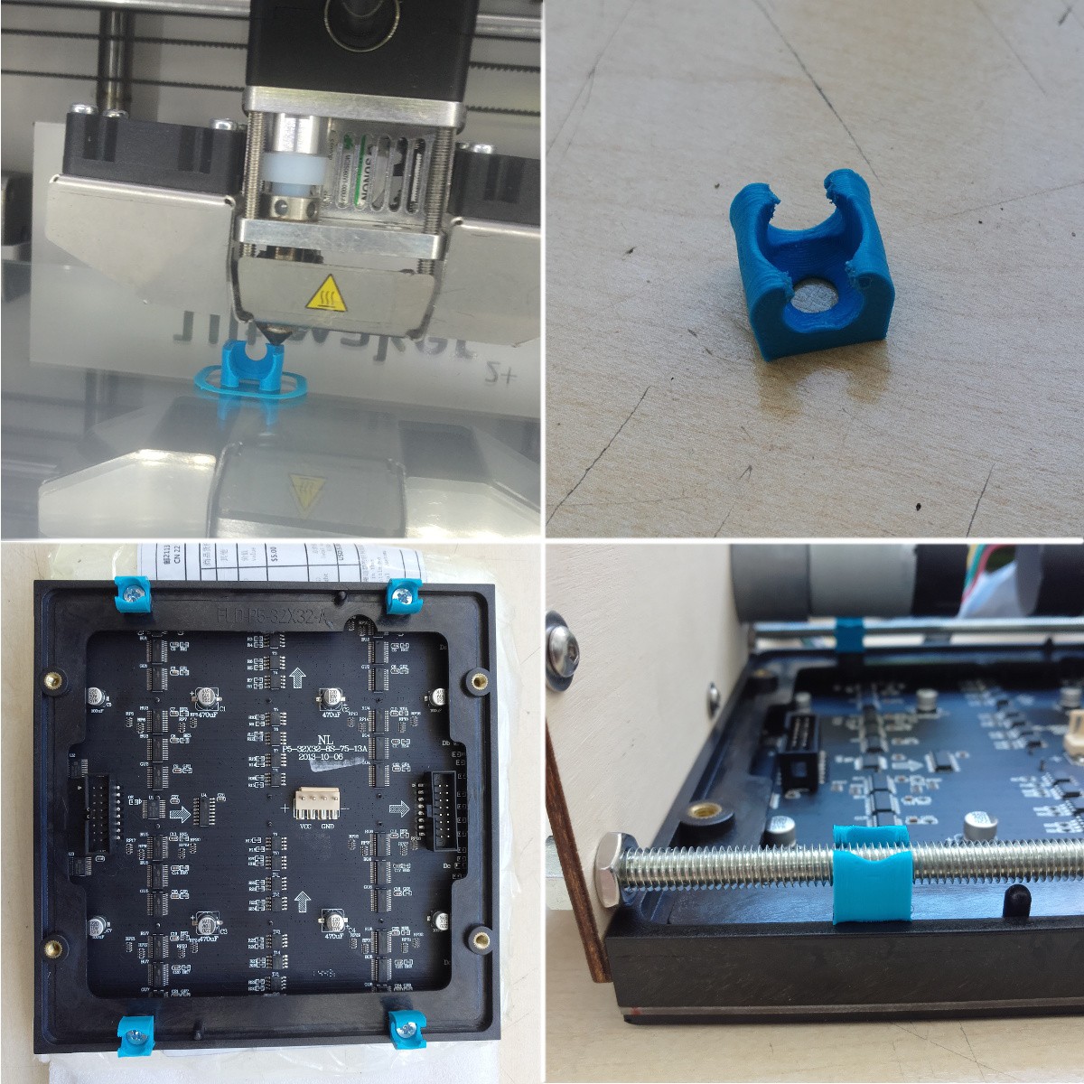
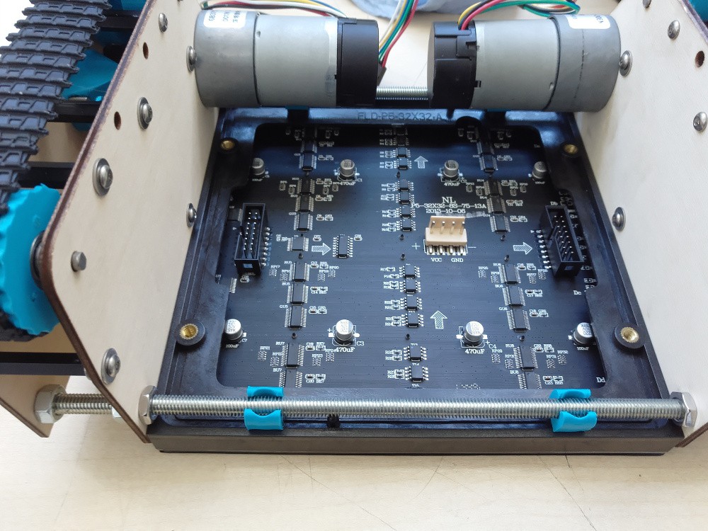
I am really tight on space in the robot, so I wanted to get a power supply and the microcontroller integrated in to the actual panel itself to get the whole assembly self-contained (for modularity) and as small as possible.
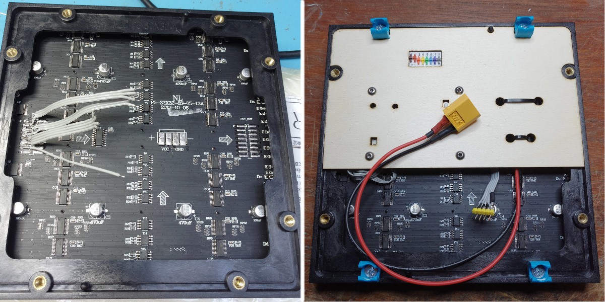
I de-soldered all the connectors, and spent a painstaking afternoon hard-wiring the microcontroller and power-supply board on to the panel. I then attached the electronics to a laser-cut panel pressed in to the underside of the matrix.
The end result is a self-contained panel module, with external connections for power ("any" voltage - there's a buck converter module integrated - I can connect the battery directly), and SPI.
One final little detail, is that when the panel powers on, before the micro takes over, or if the micro is in the bootloader, then the panel ends up displaying "random" data, which is ugly, hurts your eyes, and pulls a lot of current (no scanning == solid LEDs). So, I've connected a weak (22k) pull-up between the OE pin and Vcc, and made that pin on the micro open-drain.
Discussions
Become a Hackaday.io Member
Create an account to leave a comment. Already have an account? Log In.