 charliex
Arko started putting the rev3 board together last night, we usually build the power section first and measure how it looks, make sure none of the power is shorted in the PCB ( it happens). This board has one always on regulator, its a 3.3V LDO that one didn't show up, the 5V in from the USB was there. But nothing else, hmm. did we not jumper the battery boost ICs since they're not yet populated ? Nope that was ok... I had the schematic open and sure enough... I see a problem, i highlight it on the board image in Eagle and Arko spots it next, we have friends over at the time and they're looking at us wondering we w're going 'uh oh'
Funny how everything looks obvious when you're looking for a fault ( the airwire I added after we found it, it just hasn't been routed yet, which in itself is also going to be a bit of a hassle, since technically unless i route it, its not a 2 layer board! )
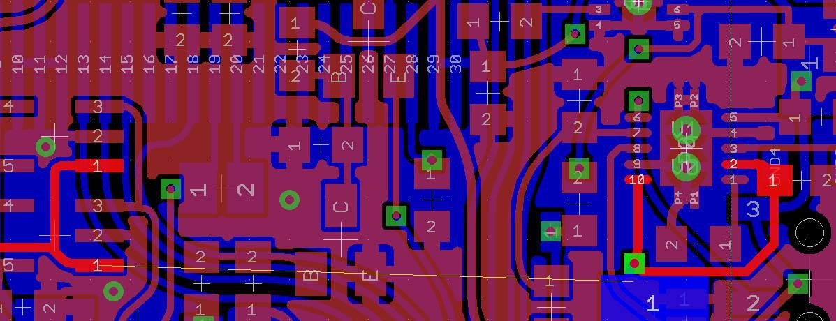
The post boost 5V line isn't connected to the VDD, and i'm also thinking why does 5V still exist as a name ?
Well the reason is simple, and its caught me out a few times , even during this board.
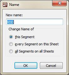
I'd renamed 5V to VDD, but I did not change the "Change Name of" option from "this Segment" to "all Segments on all Sheets", simple as that. Once that OK button is clicked i severed the link between VDD and 5V and the board no longer had power, even though we all go over it a few times, no one spotted it. The worst part of this is that it casts doubt everywhere else, and maybe that signal that runs all over the place that just has a default eagle name of n$7 has been severed and it'll be really hard to spot. So i've never liked that particular option, Eagle doesn't remember what I last choose and there probably is a good reason they choose this way.
So we jumper from the VUSB in to a big pad of one of the caps and we're off, the 3.3V turns up, current draw looks fine.
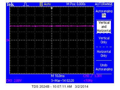
Tektronics software is awful by the way, i will tell you this boy, capturing a screenshot across the USB instead of the actual signal ? Madness, there is more data in the crappy image than there is in the waveform, i just don't understand the point of a screen capture transfer.. The best part is that on the scope if you use the save to disk option, it also captures the save to disk menu instead of the say for instance, much more useful measure screen. Of course you can use the other tek/visa software to download the waveforms instead, it'll install 10 or so background services that run all the time, and chew up a bunch of resources, then it'll transfer waveforms at the speed of mud, so much "scientific/test instrument" software is as clunky as this. The waveform Data Capture mode is equally slow but provides a much better image, but also much less data, wheres the useful measurements the scope provides, no axis levels, and for some reason a large white border? Wouldn't I rather have that are as screen real estate for the graph (or axis labels/measurements). again the other software does all this, but its just a royal PITA to use properly.
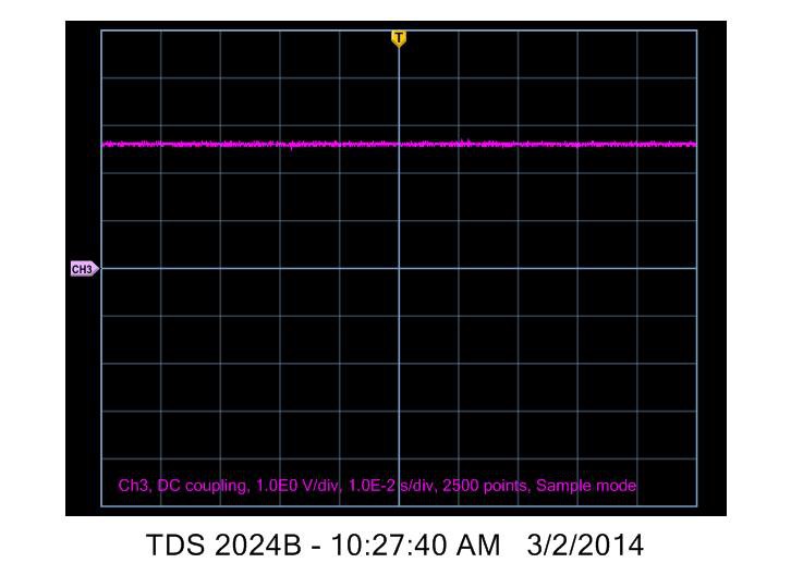
So screenshot has more information, crappier waveform and 1980's CGA bitmap stylings, waveform has less helper data, and a much nicer rendering with a giant border. Open Choice Desktop, thats my choice, poor processing vs a dozen installed services that do nothing 95% of the time my computer is running, it's become a real problem that software relies on background services that always run, so you just get bogged down with every updater app, or licensing daemon, its just not needed and poor design style.
Anyway, the FPGA and ARM are added next, ARM doesn't power up, this time I know what it is since we did this on the last board, there is a ferrite on VDDA that is missing and the ARM won't do anything without it, sure enough add it and the JTAG boots up and sees the chip, i flash in the rev2 software since the power on line is still the same and the FPGA jumps into life, it doesn't over heat so that's a good start.
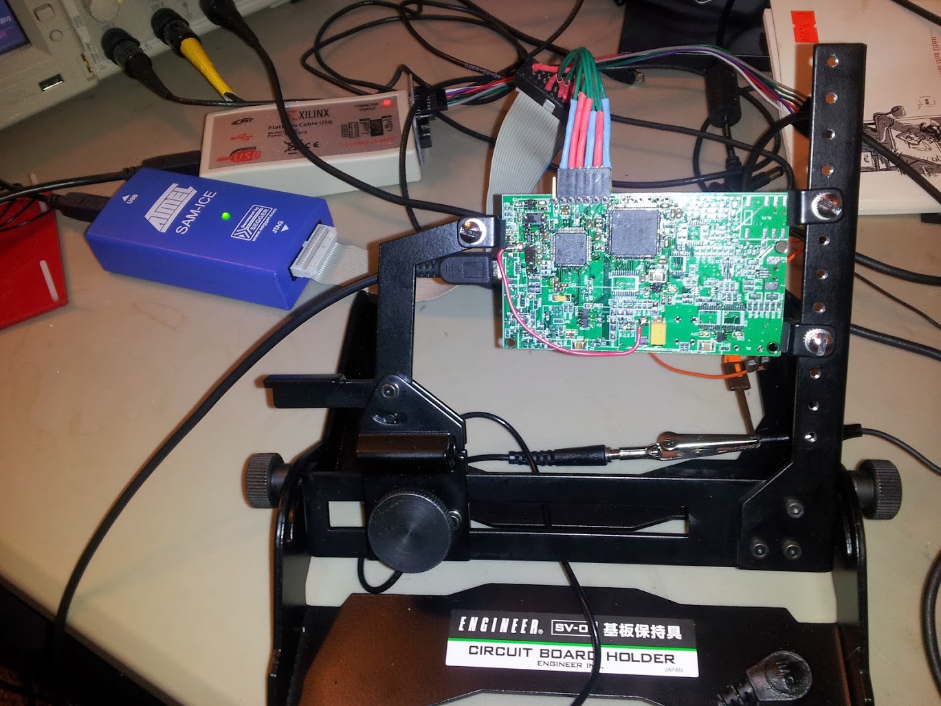
I add a define BOARD_REVISION ( 3 ) and start writing this blog, i also mounted the PCB into a neat PCB holder that Gleep had found in Japan and brought back for mmca, i ordered one directly form Japan, it's really neat, i use the panavises a lot but they are much to big for these size boards and deskspace hogs. Now i don't have to worry about ground wires flapping around and shorting out as well as giving a nice stable place for me to probe with the scope.
It's the engineer SV-D1, very handy
Discussions
Become a Hackaday.io Member
Create an account to leave a comment. Already have an account? Log In.