 Richard Dudley
Transformers are usually described in what I'll term the 'voltage domain' - that is in relation to the voltages across their windings. Under this tradition, the term 'step up transformer' refers to one with a higher voltage on its secondary than its primary. It seems to me equally valid to describe transformers in the 'current domain' too, in which case a 'step up' would be one which gives a higher current on its secondary than its primary. The transformer which does 'step up' in the current domain simultaneously does 'step down' in the voltage domain. The two 'domains' are completely equivalent and just a matter of perspective, but I find I need to adopt one perspective or the other in order to think straight about trafo design. Swapping between them gets very confusing very quickly!
Why talk about transformers in terms of currents, thereby swimming against the tide? Simply because the DACs I'm using are current output types, not voltage. From now on, when I talk 'step up' or 'step down' I'll be writing in the current domain, the opposite of the normal way of speaking of trafos. A trafo to provide a low impedance on its primary and a much higher one on its secondary is called a 'step down' in the current domain. The input current is higher than the output. Given we've not got a lot of current coming out of a single DAC chip (at most 1.2mA peak-peak) we'll need a few of them in parallel when using a step-down transformer in order to get a useful amount to feed into our I/V.
Circuits I've seen which use transformers (step down ones) in conjunction with DACs (AudioNote had a patent on this, now expired) tend to put the I/V resistor on the transformer's primary and then have more turns on the secondary to increase the voltage. To use passive I/V on the DAC's output directly seems to me to be taking a step backwards (been there, done that), so I prefer to use the trafo in 'current mode' and have the I/V stage (either active or passive) on the output (secondary). One transformer manufacturer says this sounds better - perhaps because the trafo's leakage inductance is providing useful low-pass filtering in this mode. A rule of thumb I've learned with trafos in 'voltage mode' is that they do need to be driven by the lowest possible impedance. The dual of this rule would seem to be that running in 'current mode' a trafo should be driven by the highest possible impedance - a TDA1387 output is certainly that.
Designing a transformer in 'current mode' has taken some getting used to and I'm not yet anywhere near as proficient in thinking about trafos in this way - the equations for their design are still talking about voltages, not currents. So I did one or two experiments in an attempt to prime my intuition. The first thing I discovered was that primary inductance matters - its a major contributor to the low-frequency roll-off. In conjunction with that, primary DCR matters too. In an attempt to maximize the primary inductance I have gone over to a higher mu core material, its downside is that it permits a reduced maximum B (around 0.25T) compared to the lower mu ferrite I'm used to using (~0.35T). I have very few core sets with the high mu material so I began with an EP17. This core has one major advantage in that its a horizontal configuration (most ferrites adopt vertical configs) so the winding doesn't need to go up and down, just left to right. Better winding flexibility.
My rule of thumb for a trafo design on a ferrite core is that the winding which goes on first should occupy about 40% of the total window. That's because of having a shorter turn length. Assuming the primary is going on first, a 0.47mm outside diameter allows about 20 turns in a single layer. Two layers of this do indeed take about 40% of the window, 20 turns is about 4mH in practice. The secondary I designed using the voltage equations - turns per volt at 20Hz (minimum frequency) is around 1200. Hence 3600 turns gets us to 3V peak. Rather fortuitously, the thinnest wire I have just fits on (0.05mm inner diameter). In combination this makes a 90:1 step down transformer - 90mA in for 1mA out.
The impedance transformation ratio for a trafo goes as (turns)^2 so that's 8100X. An 8k1 resistor on the output looks to the DAC as 1ohm. So far I've been too lazy to develop a closed-form equation for designing, preferring to tinker with the numbers - its more of an 'intuition pump' as Daniel Dennett might say. If we were to have an 8k1 resistor on the output it would need 346uA to reach 2.8V peak (the DAC output voltage standard) - it would need 31mA peak on the input. That's 52 DACs if we run them on 6V (0.6mA peak each). Each of those DACs would in effect see 52ohms as an output load, quite acceptable. But can we do better? If we were to add more DACs, we get to see how the transformer gets us to a place which looks better than even. Doubling the DACs to 104 means we'd use a 4k05 resistor (if we keep the same trafo ratio) as we still want the same 2.8V peak. But this takes twice as much current to no advantage - better to adjust the trafo ratio to still drive the 8k1 - go to 180:1 (same output current but needs twice as much input). Increasing the ratio by two quadruples the impedance ratio so then even with double the number of DACs, each is seeing half the effective impedance. This looks like a 'free lunch' so long as DAC chips are cheap - which indeed they are. I recently bought a bag of 1000 for 150RMB (about $20) including shipping.
But how far is it practicable to push the trafo ratio? That's what I intend to find out......
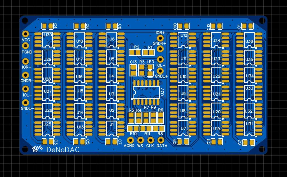
(Below is a board just off for fabrication which parallels 36 DAC chips. Its designed to be stacked for building DACs with outrageous numbers of paralleled chips.)
Discussions
Become a Hackaday.io Member
Create an account to leave a comment. Already have an account? Log In.