 Richard Dudley
Building up the filters takes time due to the painstaking process of ensuring the reactive components (inductors and capacitors) are close enough in tolerance to get to within spitting distance of the target filter response.
Inductors I measure to 1uH and bin them. The mode for the two values seems so far (with about 40 measured of each to date) 30uH and 43uH, slightly under 10% below the nominal values. Capacitors I trim by adding in paralleled units after measuring them. After soldering its essential to allow enough time for cooling and relaxation of thermal stresses before measuring
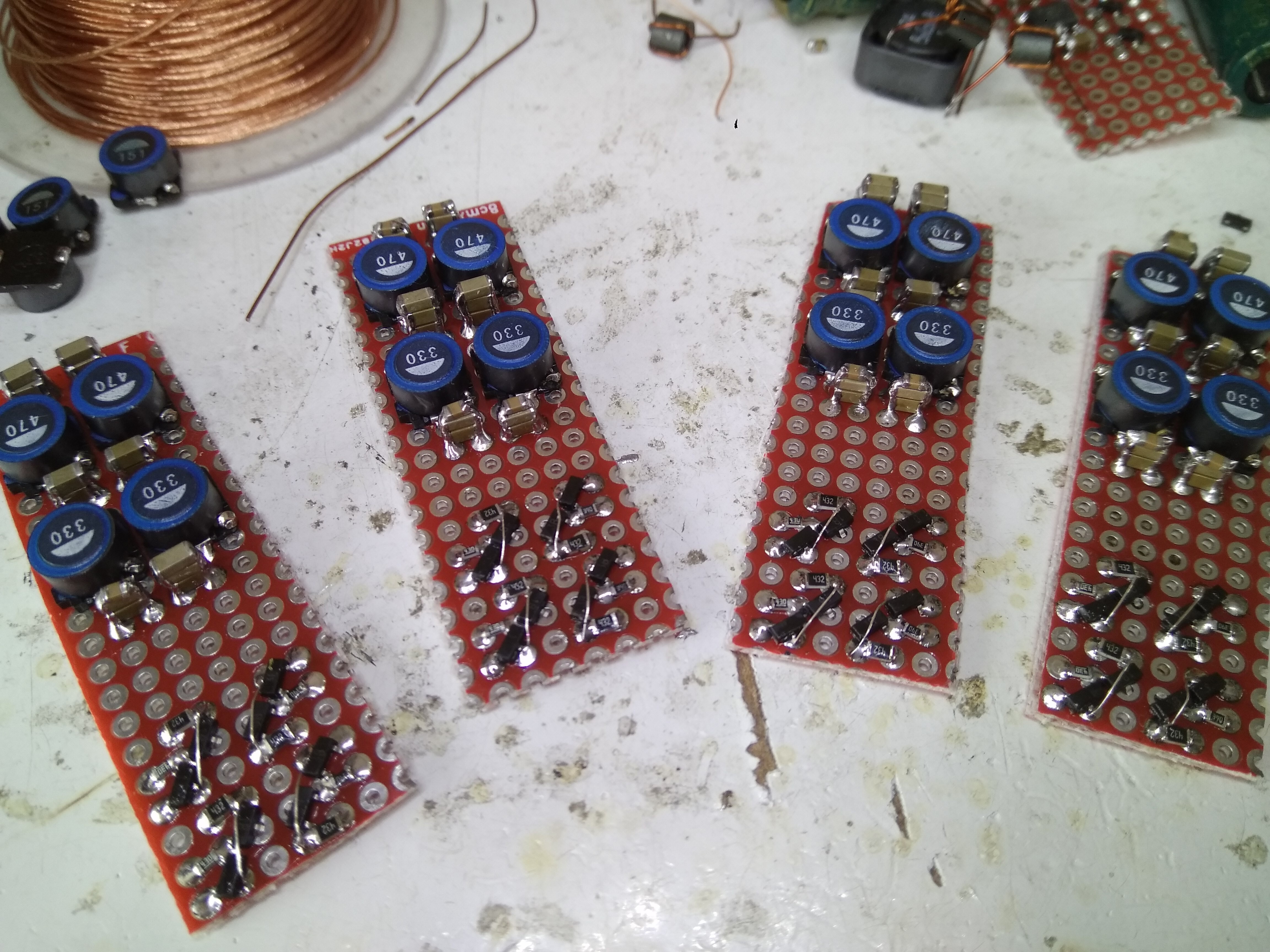
- I allow 10mins minimum for this, but if I see the capacitance still decreasing I'll allow more time. What I call the 'tuning networks' (RC in parallel with inductors) are soldered under the board, using 0805 and 0603s. The main shunt capacitors are generally 1206 and visible in stacks in the above shot. Occasionally the 1206s I'll trim with an 0805 on top, aiming to get within 2% of the value on the schematic.
At the front of the boards in the picture are the current sources used to bias the I/V transistors (not yet fitted in this pic).
Discussions
Become a Hackaday.io Member
Create an account to leave a comment. Already have an account? Log In.