Things used in the project:
Hardware components:
Software apps and online services:
- Arduino IDE
- DFRobot Image Converter
Hand tools and fabrication machines:
- Stylus (generic)
The Specifications
- Model: DM-TFT28-105
- Display size: 2.8"
- Operating voltage: 3.3V or 5V
- Resolution ratio: 240x320
- Communication Interface: SPI
- Flash memory: 4MB
- Operating temperature: -10~70℃
- Support micro-SD card
- Support Arduino
- Size: 55*70 (W*H)mm
- Viewing area:43.2*57.6 (W*H)mm
- Weight: 40g
Pinout


Bubble Display

- First download the DmTftLibrary from dmtftlibrary.
- Extract the content to your Arduino library folder. In Windows this is usually located in Arduino IDE folder\libraries. Check Arduino's official guide if you want more information on how to install the Arduino Library. The official guide of Arduino.
- Start Arduino IDE, open the sample code, click "File--> Examples-> DmTftLibraries", select the right board and COM port: DM-TFT28-105
- Open the Example and upload to your Arduino board.

Graphic Display Example

In the sketch -
tft.drawString(5, 10, "Romantic cabin");
- It sends command to print "Romantic Cabin" 5 px away on x-axis and 10 pxfrom y-axis. You can also print a only text on screen ( if you give proper distance of 20 px between each line.
tft.drawLine(x, y, x-80, y+30, YELLOW );
- It gives command to draw line from x and y co-ordinate to x-80 and y+30co-ordinate. It also specifies that the color of line is yellow. (Remember to enter color in CAPS or HEX code only). Understanding it is easy but easier if you know basic 2D geometry and about Cartesian Plane.
tft.drawRectangle(x-40, y+50,x-20, y+70, 0x8418);
- It gives command to draw a rectangle where corner points and color of it's outline are given as the arguments.
tft.fillCircle(x+100, y-30, 20, RED );
- This one fills color in the circle whose center and color to be filled are given as arguments.
The Drawing Board

We can make a home made digital drawing board in just a few minutes. All we need are Arduino and this TFT shield.
How :
- Stack the shield on the Arduino.
- Connect the Arduino with the laptop and upload the sketch for drawing board.
- Wait for the screen to turn black.
- Now, swipe your finger on the screen and a line will be drawn. I didn't have but I would prefer you to use a stylus.
In the sketch -
dmTouch.readTouchData(x, y, touched);
- It reads the x and y co-ordinates of the point touched.
tft.fillCircle(x, y, 2, BLUE);
- It draws a point on the area where x and y co-ordinates belong to.
The syntax is :
<object_name>.fillCircle(x ,y, <point thickness>, <point color>);
Moreover, you can draw on it and to clear it, use the reset button on the screen to clear the graphics.
Display a pictures from a SD card

It requires a special format for the displaying picture: 16bit RGBRGB bmp.
You could download the convert tool here: ImageConverter

Why 16 bit, not 24 bit?
There are 2 reasons for converting your images to 16-bit bmp with flipped row order:
- Size : The image is only 2/3 of the original size and because most embedded displays/drivers uses 16-bit color, the picture quality will be the same.
- Speed : Most embedded TFT uses the 16-bit 565 format and support the top-bottom write order.
a) The MCU does not need to convert the 24-bit to 16-bit 565, this is already done.
b) If the source format is already in correct order, a faster algorithm for reading the data can be used.
c) There is less data to read (because the image is only 2/3 of an original size)
Compared to raw picture data, there are several advantages:
a) It has meta data about the format, size, how it is stored etc. With raw data, the program must already know this.
b) It is a standard so it can be viewed directly in most viewer (although not all viewer )
c) Can create and edit the images in advanced photo editing...
Read more »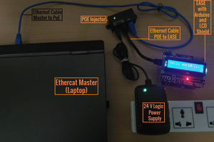
 Esmacat
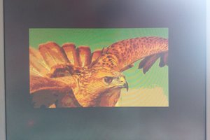
 Nikolay Popov
 Embedotronics
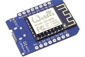
 Maria Carlina Hernandez