0%
0%
Mini DRO for lathe
A small DRO for the lathe that doesn't take up too much space
Become a Hackaday.io member
Already have an account? Log in.
Just one more thing
To make the experience fit your profile, pick a username and tell us what interests you.
Pick an awesome username
hackaday.io/
Your profile's URL: hackaday.io/username. Max 25 alphanumeric characters.
Pick a few interests
Projects that share your interests
People that share your interests
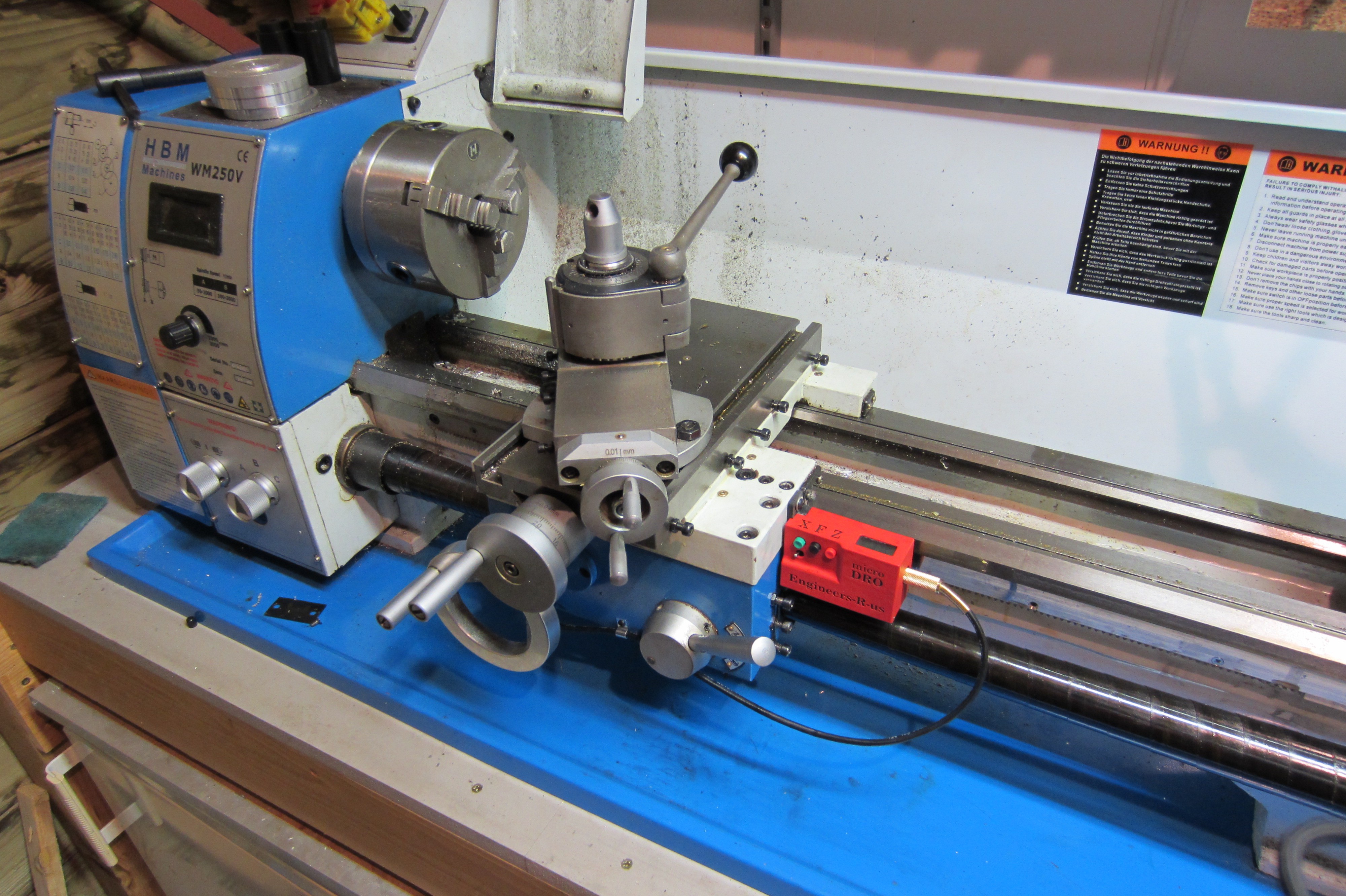
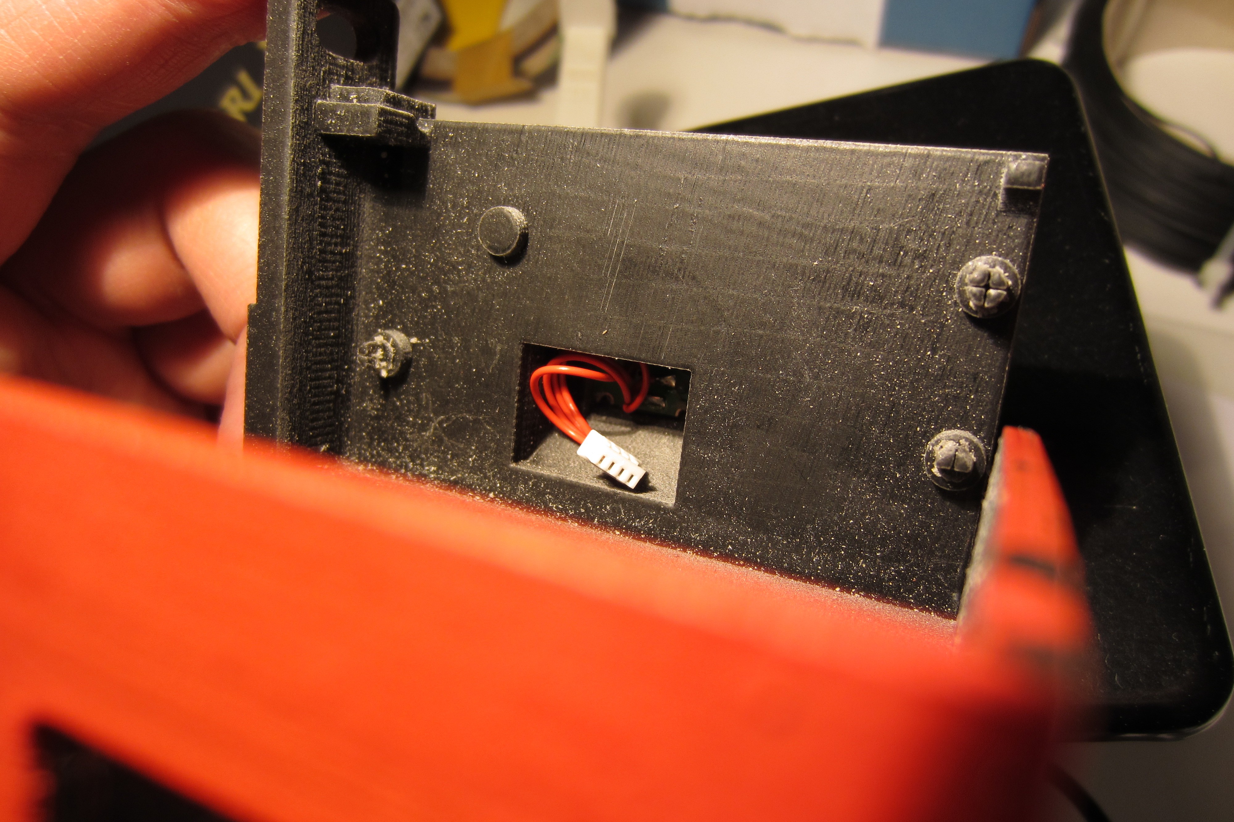
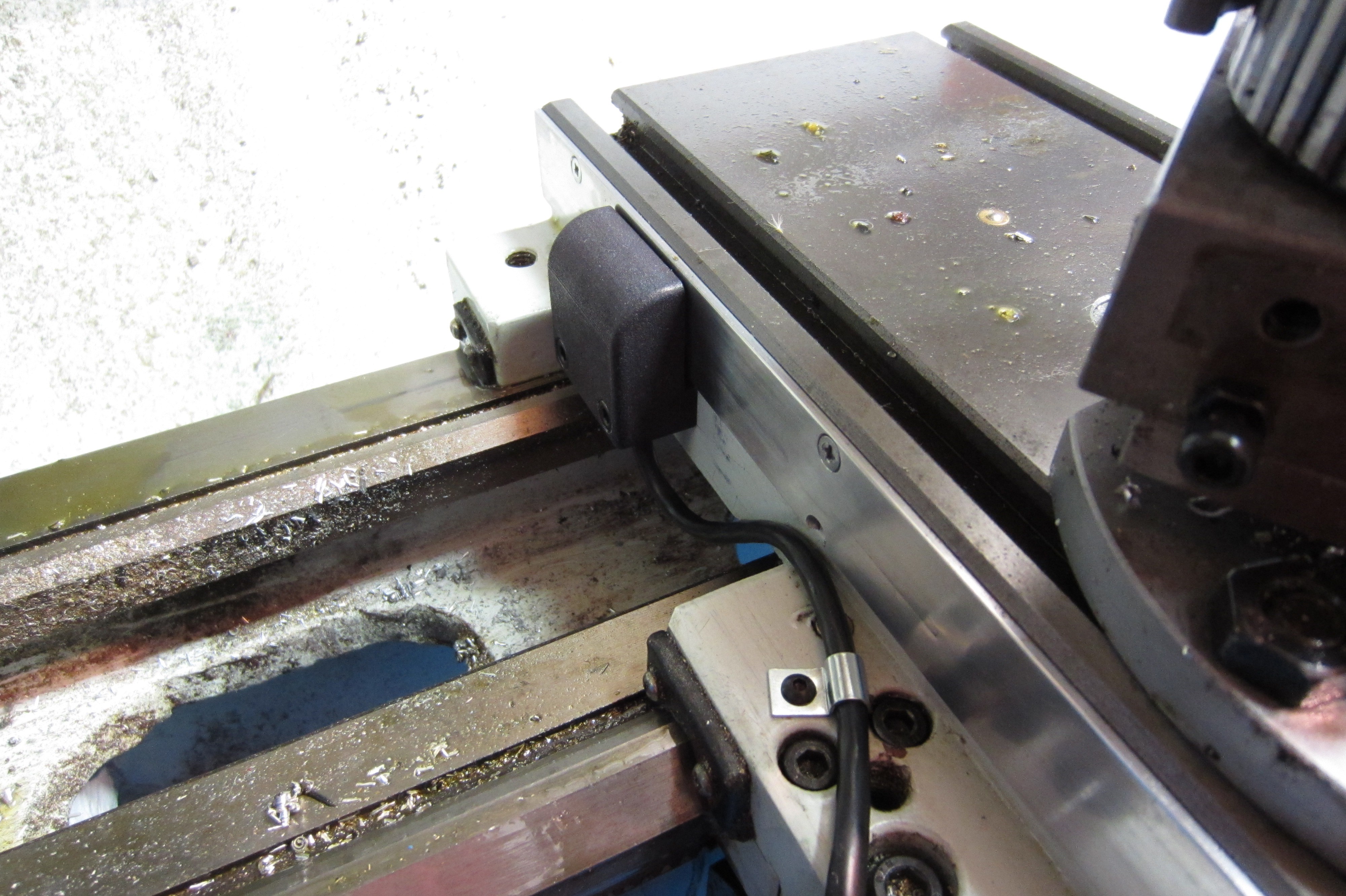 So, normally you don't mount the sensor on this side of the cross slide, but on the other side it would interfere with the tailstock. The magnetic target only adds 2mm to this side and the sensor is rather small, so it's not really in the way.


 dennis
 Jan
Jan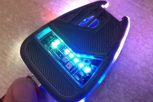
 Xasin
Xasin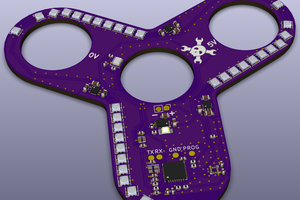
 Matthias
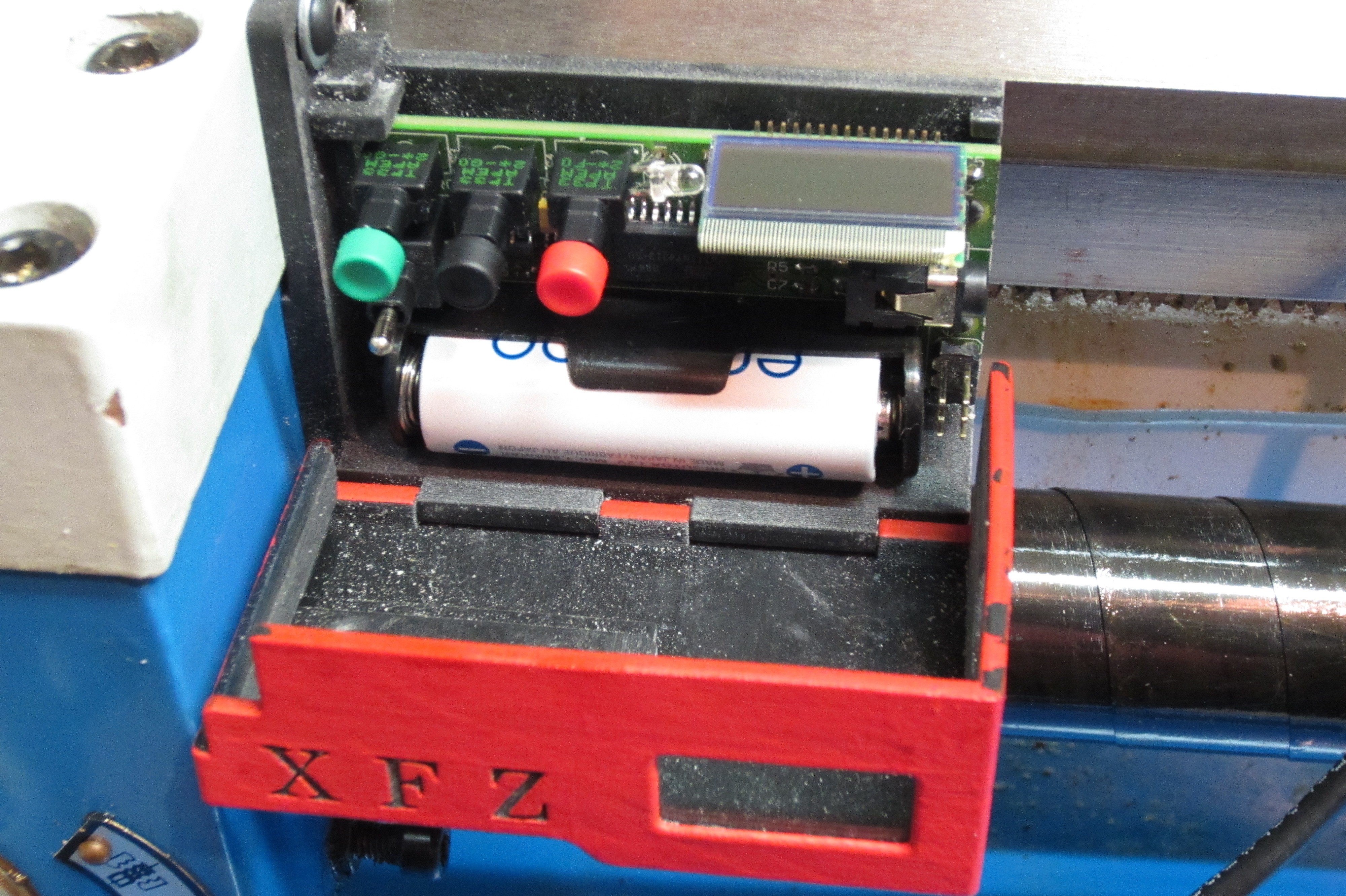
It's great to hear about your project to make lathe work more efficient using a DRO with a smaller footprint. The AS5310 magnetic encoder chips from Austria Microsystems sound like an excellent source of inspiration.
Having a DRO with a smaller display and fewer wires would certainly make lathe work more efficient, and it's impressive that you're taking on this project. The magnetic encoder chips offer a unique advantage over traditional DROs since they can measure linear and rotational movements without physical contact. This technology can also help reduce the number of wires required, which would make the installation process easier and cleaner.
I look forward to hearing more about your progress on this project and how the AS5310 magnetic encoder chips are integrated into your design. Good luck!