 Facundo Noya
Diabetes is a chronic disease that has become a global epidemic with complications in the feet that include, among others, infection of the same. Ulcers in the feet of individuals suffering from this pathology are extensions and are estimated to affect 25% of patients throughout their life, due to neuropathy and the potential existence of a vascular disease. Foot infections are the major causes of morbidity, including a reduced quality of life in physical and mental appearance, antimicrobial therapy, wound care, and in many cases surgical procedures that result in loss of ex tremor due to the need to amputate them. Patients with diabetes are susceptible to infections related to immunodeficiency, neuropathies and arteriopathies. An infected foot with ulcer has a 60% chance of being amputated, making infection the main cause of this tragic outcome. For the treatise of this pathology, the main attention is required to the appropriate diagnosis, an accurate classification of the lesions, obtaining the samples suitable for the culture and prescribing a definitive antimicrobial therapy or the rapid determination when the surgical interventions are necessary and intensive care in wounds.
In diabetics, the foot passes through several pathological stages, in which the tissues of the lower limb have been affected: beginning with the skin, followed by the subcutaneous tissue, muscles, bones and joints, nerves and blood vessels. Infections in the feet, the child plus the consequence of the cause of foot ulcers.
These infections begin with a cleft in the skin, usually at the site where the trauma was generated (whether due to mechanical or thermal causes) or ulceration. An infection is defined as the invasion of microorganisms, their multiplication in hostile tissues that trigger inflammatory responses and produce destruction of them. It should be noted that these complications in the feet occur in the soft tissues and lower malleolus. Several factors facilitate foot infections in a diabetic patient, including neuropathies, vasculopathies, immunopathies and biomechanics in the foot.
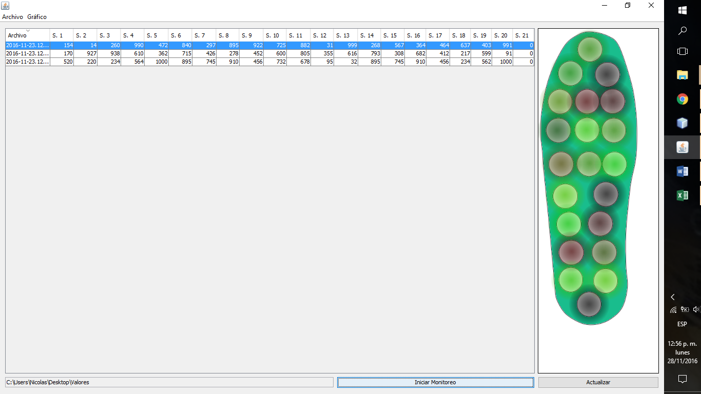
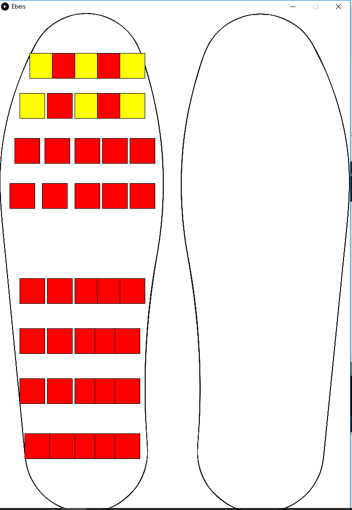
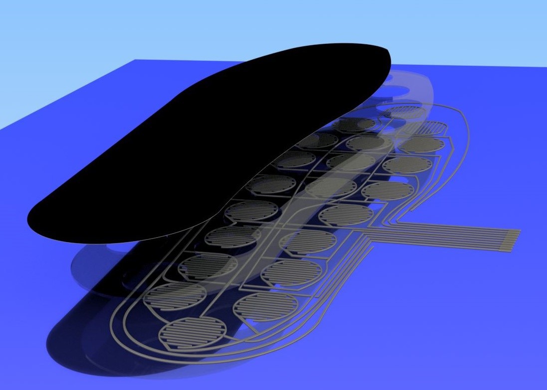
As mentioned above, infections are an attainment of the formation of ulcers. A common type of pen is the one that originates from the high pressures exerted on a sector of the foot. Routine monitoring by the patient or health personnel is the key to preventing inheritance from forming, and also to avoid amputations by extension, reducing the latter by 50% to 80%. That is why new monitoring tools are required, being the measurement of pressures on the surface of the skin of the sole of the foot one of the many solutions that can prevent the development of this pathology improving the quality of life of the person and avoiding so that drastic measures are taken
0%
0%
Become a Hackaday.io member
Already have an account? Log in.
Just one more thing
To make the experience fit your profile, pick a username and tell us what interests you.
Pick an awesome username
hackaday.io/
Your profile's URL: hackaday.io/username. Max 25 alphanumeric characters.
Pick a few interests
Projects that share your interests
People that share your interests
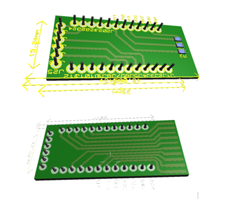
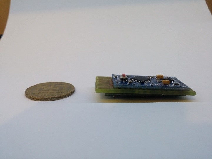
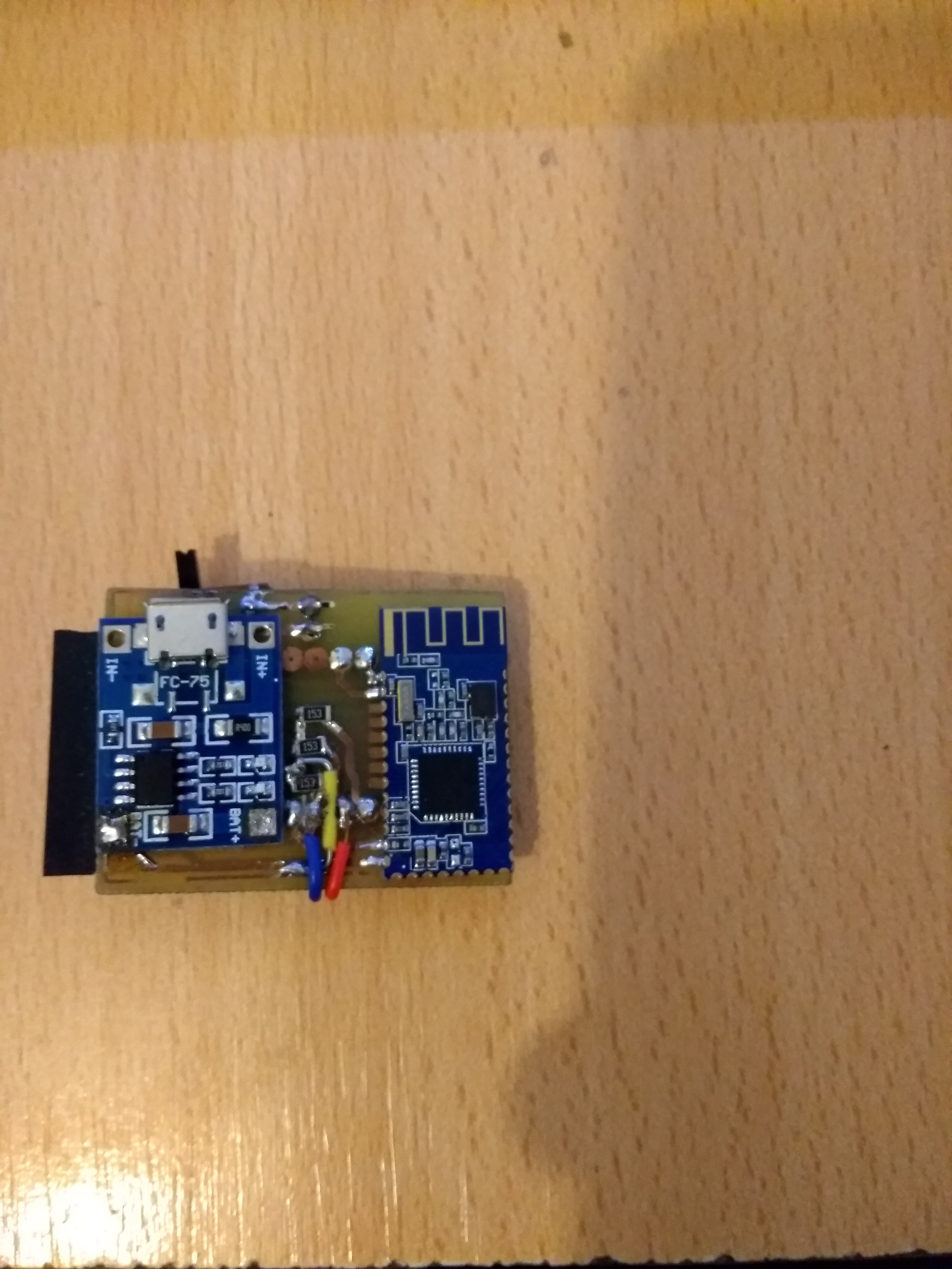
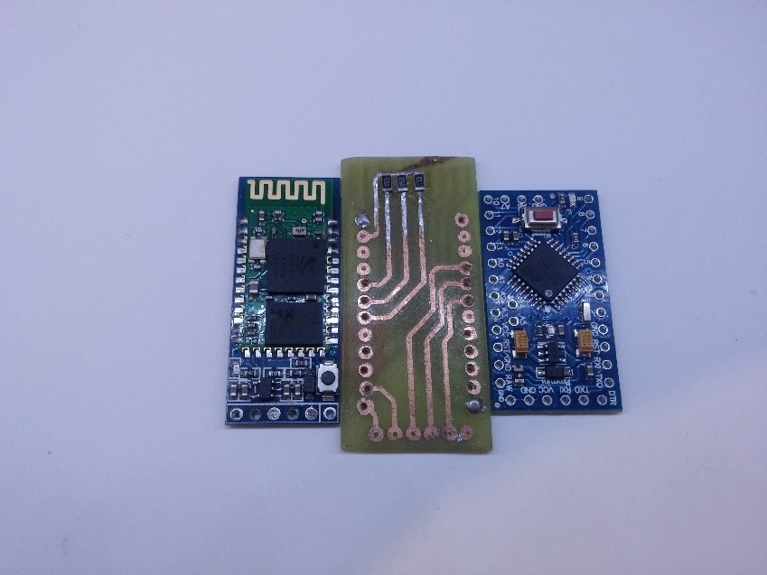 The second version incorporate a tp4056 for lipo battery and HM-10 Ble module


 Vignesh Ravichandran
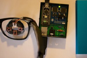
 Malte
Malte
 Debargha Ganguly
 deepankar
Thanks you @Simon Merrett !! Your project looks really interesting.
Maybe we could work together and learn from the other. If you are interested write to me!
See you