 Facundo Noya
A resistive sensor, also known as FSR (For-ce Sensing Resistor), is a polymer film device that exhibits a decrease in resistance when the force applied to the active surface is increased. FSRs are not load cell or strain gauge gas although they have similar properties.
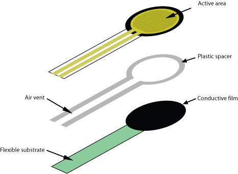
This sensor consists of four layers:
• A layer of dielectric plastic
• An active area consisting of a conductor pattern, which is connected to the cables that will go to the processing circuit.
• A plastic separator, which includes an opening aligned with the active area.
• A flexible substrate coated with a thick polymer conductive film, aligned with the active area. This polymer is most often replaced by an FSR ink layer
The basic principle for the use of an FSR is a conditioning circuit of the voltage divider type, whereby the output will be an analog volt- age of 0-5 V and varies according to the force exerted on the sensor (SensorWIki, 2016).
Figure 93 shows the connection diagram of a resistive divider or voltage divider. It consists of a voltage source and two resistors connected in series. The current supply will flow through the two resistors evenly because they are connected in this way. One of the two resistors has a variable value, and is that which belongs to the resistive sensor while the other has a fixed value. As explained in this section, an FSR sensor has as its operating principle to decrease the resistance when it increases the force exerted on its surface, which is why it behaves as a variable resistance in the circuit.

By Ohm's Law, the voltage drop in a load is proportional to the current flowing through it and the resistance it has, and by Kirchoff's Law, the sum of the voltage drops in a circuit is equal to the voltage delivered by the source. When no pressure is applied to the sensor, the top layer and the bottom layer are not in contact, so the resistance is infinite and no current flows through the circuit. As the pressure on the sensor begins to exert force, the two layers mentioned above begin to come into contact and the resistance begins to decrease, whereby current begins to flow through the circuit thus generating voltage drops by the two resistors -tencias (both fixed and variable).
In these sensors, there is a threshold or breaking force that is when the contact between the two layers is sufficient to start running and another step that is saturation, which occurs when the weight increases are very low or no decrease in resistance
Sensor construction
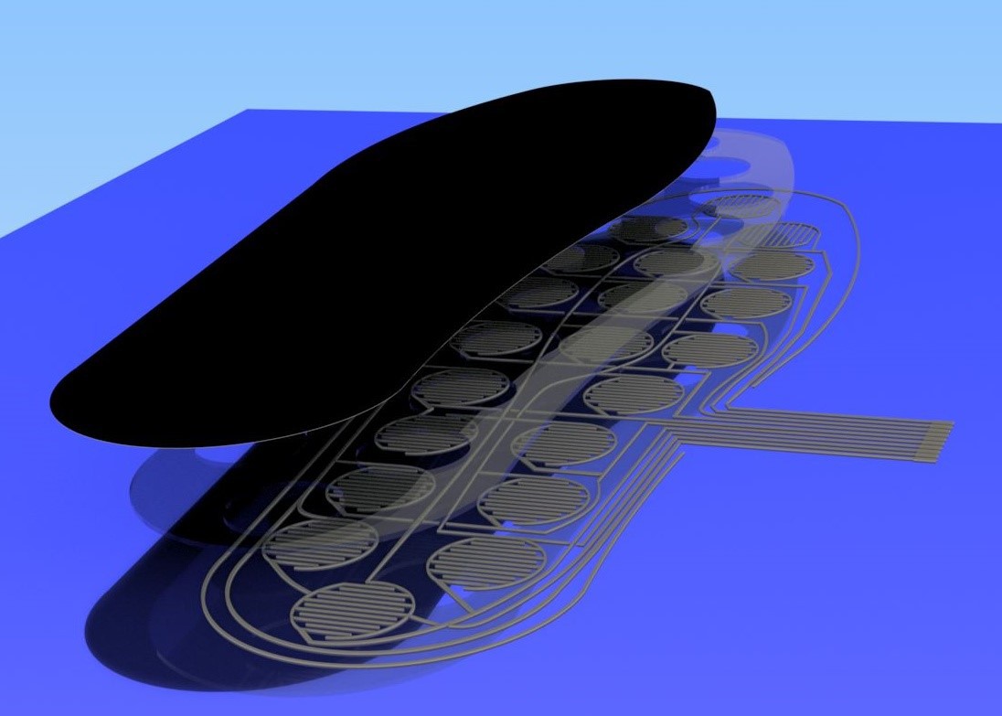
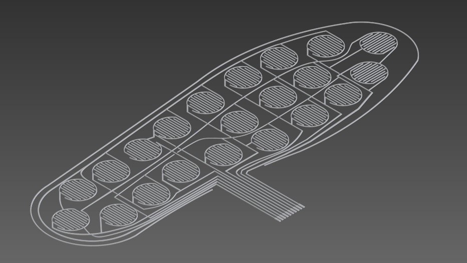
The instrumented insole has a series of layers or plates, each formed by the following stages.
The first layer, is a XactFSR from the company Sensitronics (Senstronics, 2016). It is a plate that has a deposition of carbon on one of its faces, which gives a resistive property to the passage of time. In this way we can obtain an analogue measurement as a function of the pressure exerted on this sheet.
The second layer is a dielectric material that will function as a separator. It has the characteristic of having holes that coincide with the location of the active parts.
The last layer is an acetate sheet as above. In it are traced silver conductive ink tracks with the selected shape of the sensor. The manufacturer of the XactFSR iron recommends the following specifications for the tracks:
• The width of the combs and the spaces between them will affect the sensor response. 7mil (.007 ") is a common dimension for both, but other dimensions are viable and may even be desirable depending on the application.
• Sensors with finely spaced fingers will be more sensitive to small forces than sensors with grooved fingers.
• The PCB finish will influence the sensor response. An ENIG (gold) finish is recommended.
• The thickness of the copper will influence not only the sensor response, but also affect its useful life. When the thickness or weight of the combs are raised copper, will raise the FSR material and increase the deformation of the sensor under load. This deformation allows the blade edges of the copper fingers to penetrate the surface of the FSR material, degrading and eventually destroying it. We have found that copper weights of half an ounce or less, along with the 7-mil finger spacing, produce a good sen- sor response for general purposes and a long shelf life
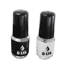
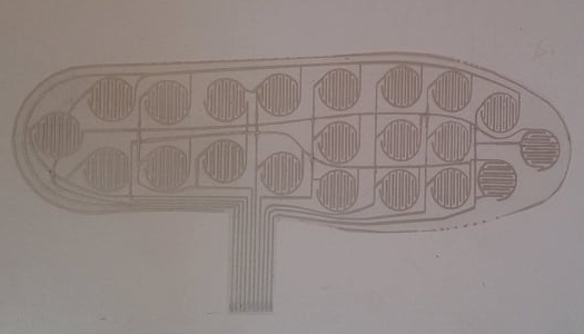
For the elaboration of the sensors, on the sheet of acetate was drawn with conductive ink with silver base. The same is from the electrochemistry DELTA® and is easily achieved in local businesses of electronic components. It is generally used for the repair of printed circuits and flexible cables, and is formed by a dispersion of silver in flakes seated in a synthetic substrate of great flexibility. Its application can be on glass, ceramics, flat cables, plastics, rubber, among others. It can be purchased in containers of 6/16/30/60 grams, which come with a brush for its application as well as with a solvent of fast evaporation that avoids the cracking of the paint after its placement, it is also used to restore the original viscosity, as well as for cleaning the brush. It has the property of being flammable.
Among the physical properties of this paint, the manufacturer indicates that the average particle size is 23 microns and has a specific gravity of 9.3 g / cc
Due to retraction problems, which caused the residual ink to be spread through areas where it was not due, it was decided to use one with the capacity to retract the syringe plunger.
It was obtained from the Thingiverse page, and for the construction it was necessary:
• The three printed parts
• Rod M5
• NEMA 17 engine
• 8mm smooth rod
• Two LM8UU bearings
• Flexible coupling 5mm to M5
• 7 M3 screws
• 7 M3 nuts
• 1 Ml. Syringe sleeve.
• 1 Anti damping for the engine
The first printed part is static and has the function of fixing the motor. It transmits the movement through a threaded rod M5 by means of a flexible coupling that allows the mobility of the rod in case of an imperfection and is not completely straight, thus avoiding the transmission of the error to the car and reducing the vibrations. On the sides, were the smooth rods that allow the displacement of the rolling. LM8UU bearings are used to minimize friction and do not affect the translatory movement of the carriage. Originally the design did not contemplate them, for that it was necessary to make the corresponding adaptations.
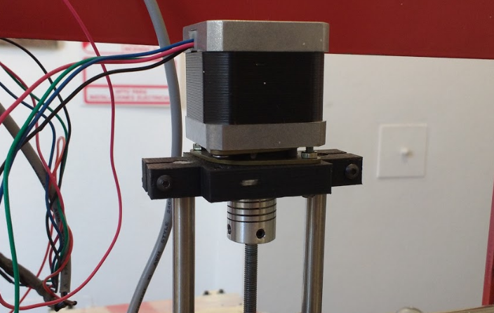
First printed part of the extruder with retraction
The second printed part, is the only moving part of this structure, called carriage. The part slides on the smooth rods using linear bearings LM8UU. The transmission of the movement is achieved by the interaction of the threaded rod with a nut M5 recessed in this piece. The direction of rotation of the motor determines the direction of movement.
In its lower part it has a support where the plunger is imprisoned, so that this content and can avoid descending or ascending movements. It is very important that the plunger is perfectly supported without the possibility of free movement, if this happens, a backslash will occur which would result in improper extrusion or retraction.
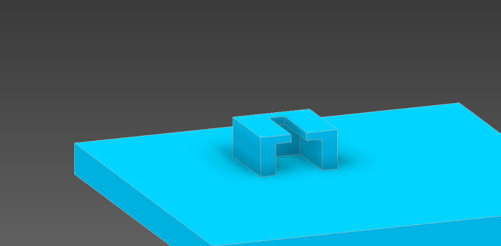
Illustration 43: Lower piston support
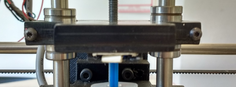
Illustration 44: Pulver Extruder Truck With Retraction
The last piece printed, where the syringe was contained, is the one that marks the end of the extrusion when the lower part of the bearing makes contact with it.
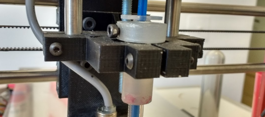
Illustration 45: Third and last printed part of the extruded pasta extruder
The extruder was adapted for a 20 Ml syringe. but due to the fact that it was higher than the amount needed, a case was adapted to be able to place the 1 Ml syringe. finally used.
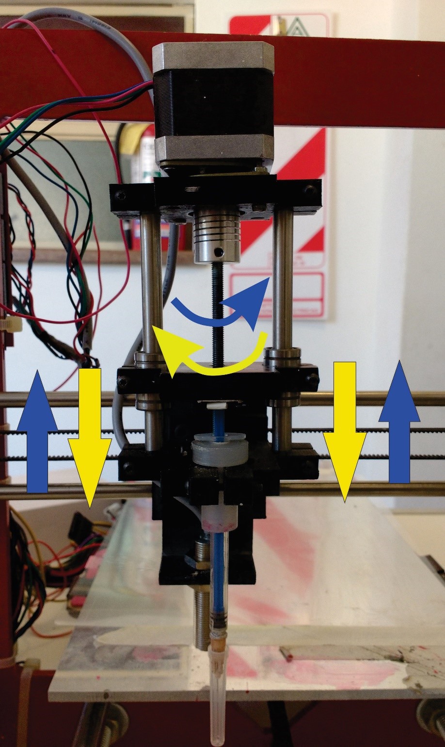
The extruder operates by transmitting the engine rotations to the rod by means of the coupling to achieve movement of the centerpiece, the operation of which has been described above. The direction of rotation will indicate the direction of movement and final result of the mechanism: the clockwise rotation produces a downward movement and consequently an extrusion, while the anti-clockwise produces the opposite
Once the active region of the sensors was obtained, the other two layers were designed and cut. For the separator, the design was vectorized and cut by laser. On the other hand, the XactFSR sheet was cut manually so that there was no risk of altering the physical properties of the material.
Discussions
Become a Hackaday.io Member
Create an account to leave a comment. Already have an account? Log In.