0%
0%
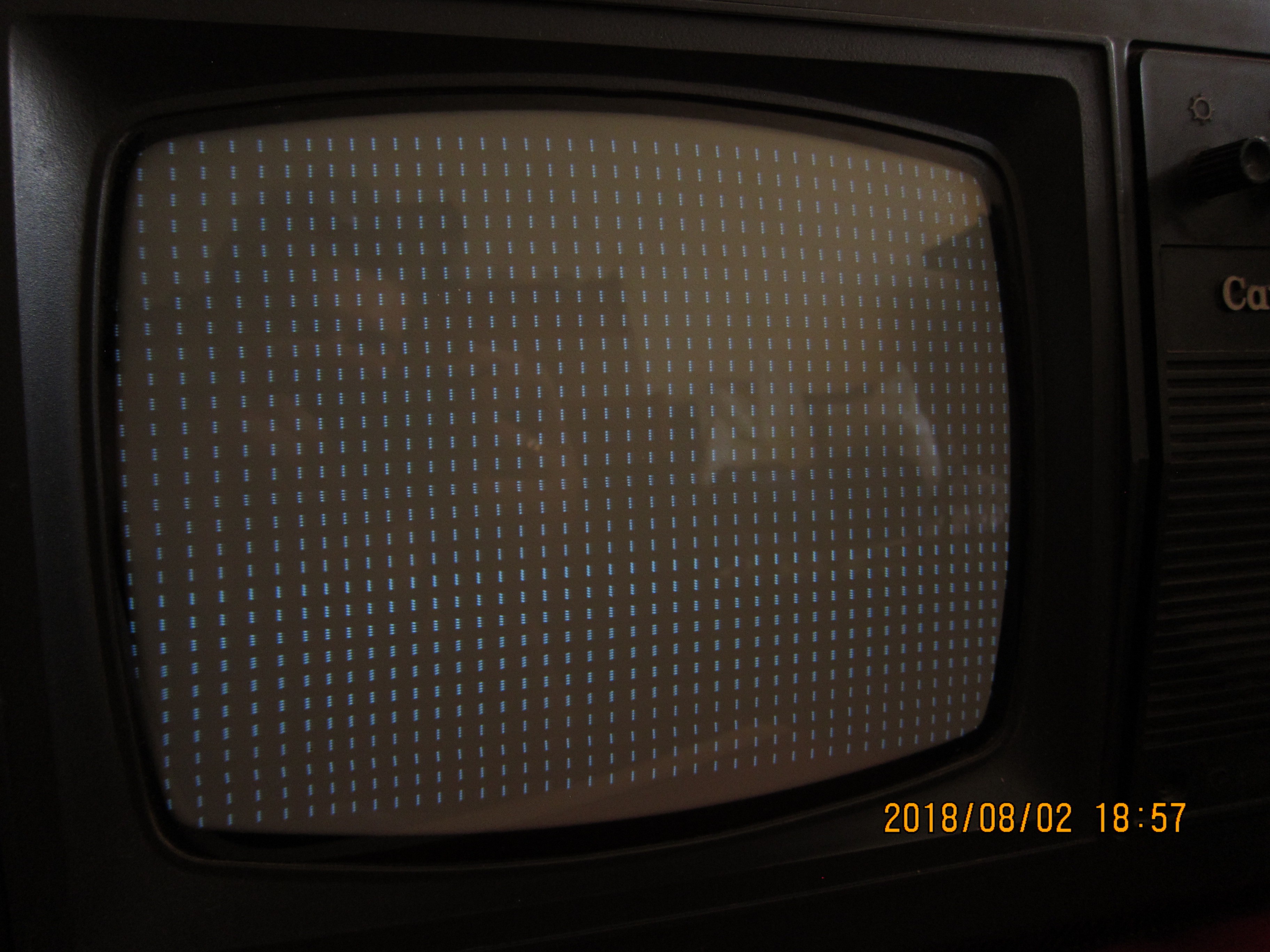
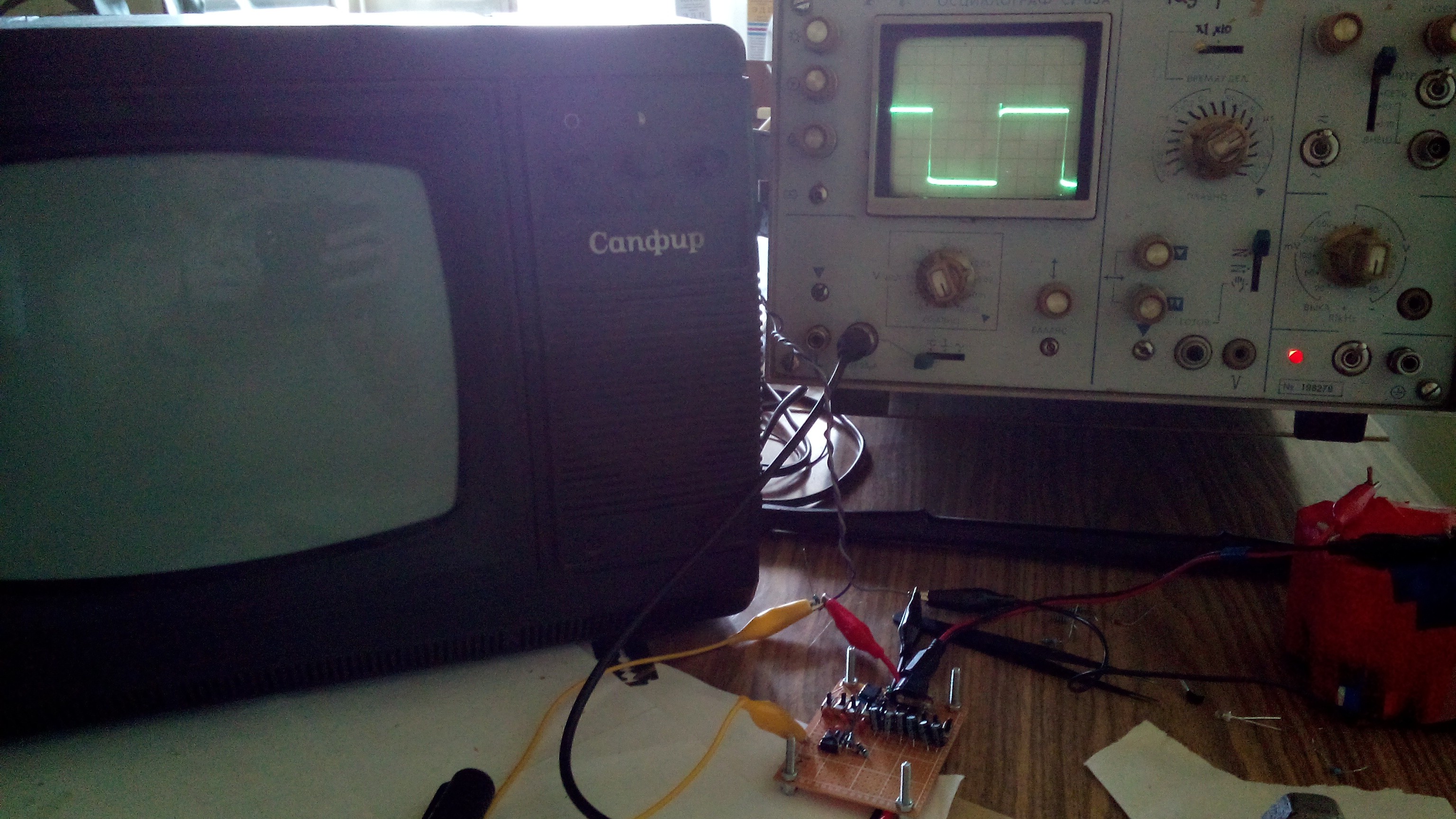
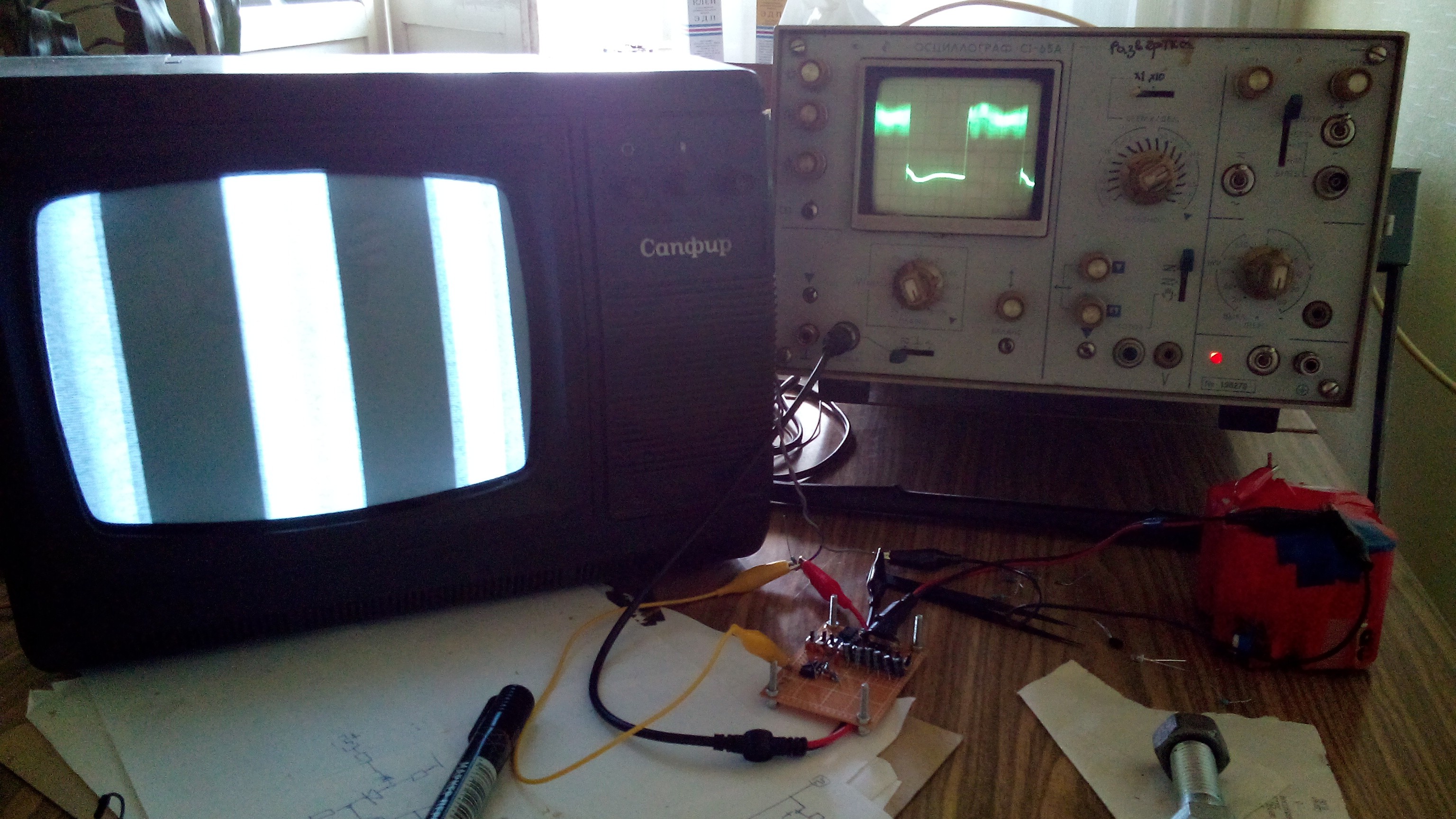
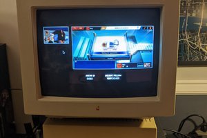
Messing around with b&w crt tv
Here are to be some experiments with crt tv.
 Pavel
PavelBecome a Hackaday.io member
Already have an account? Log in.
Just one more thing
To make the experience fit your profile, pick a username and tell us what interests you.
Pick an awesome username
hackaday.io/
Your profile's URL: hackaday.io/username. Max 25 alphanumeric characters.
Pick a few interests
Projects that share your interests
People that share your interests


 Russell Kramer
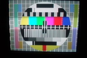
 marble
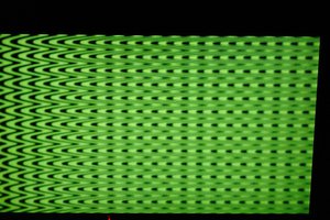
 Nathan Kiesman
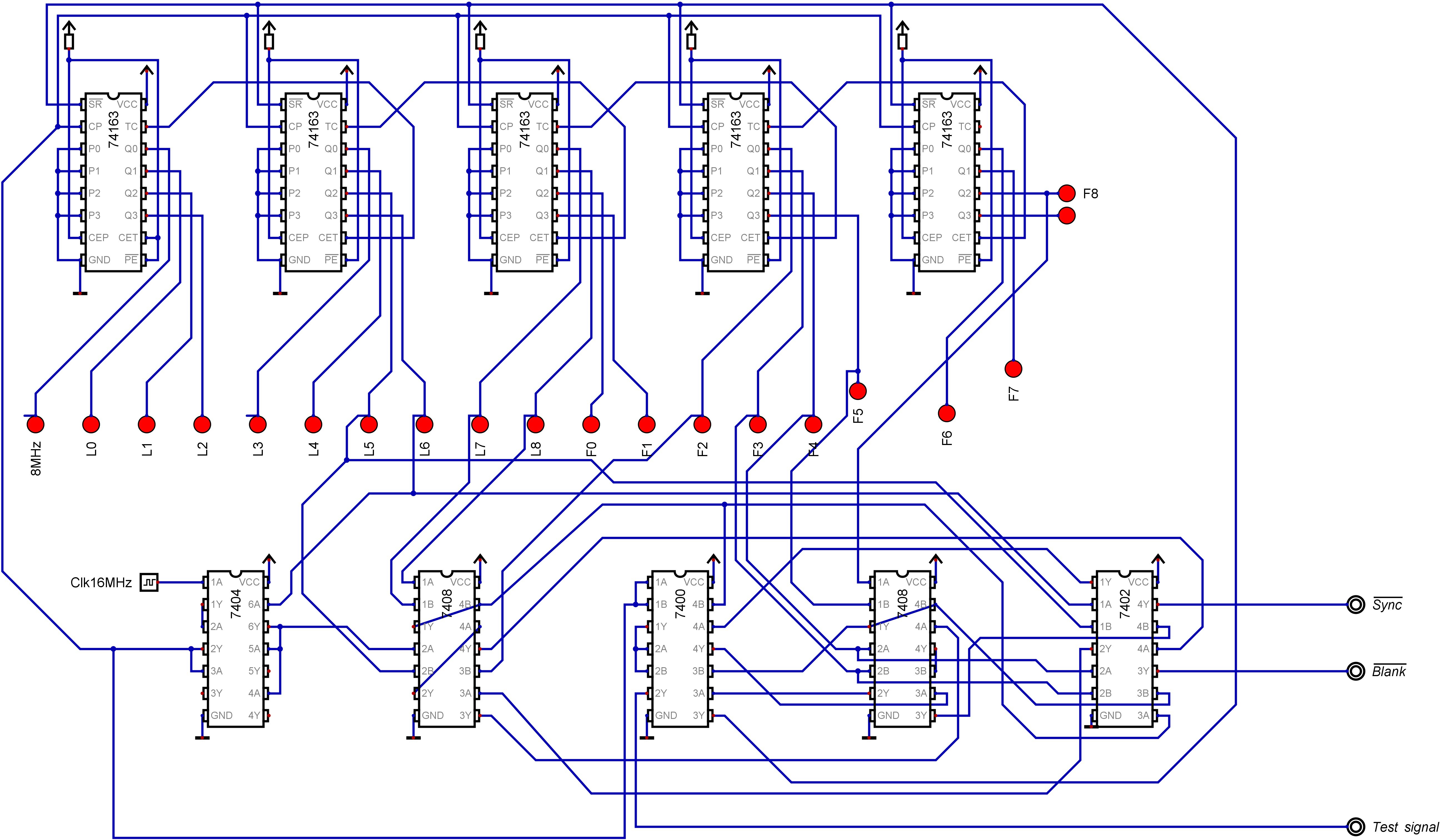
Thank you for such a thorough write-up! I happen to be tinkering with the same model TV as this, though my skill level is far beneath yours. May I ask how you added composite inputs? I love your schematics for the signal generator—I will likely attempt to build one myself.