 The Lightning Stalker
Design Challenges
Quite often it is a significant challenge for the mentally and physically disabled to remember to take their medicine on time. Providing audible and visual alerts at the proper times greatly aided the test subject in remembering to take medicine. It is believed that the timer described herein will contribute to a better life for the many sufferers of mental and physical illnesses worldwide.
License
Eclipse Public License - v 1.0 was selected as an appropriate license document for the project. Please read the license document. (Available on the GitHub)
Bill of Materials
A current BOM for the prototype is available at FindChips.
Breadboarding
The Arduino Mini, Micro, and Nano all plug easily into a standard breadboard, and this is the recommended configuration for testing. Peripherals, including the buzzer, pushbutton switch, additional LEDs, and others as deemed necessary, simply plug into the breadboard. A standard 400 hole breadboard may be used for this purpose.
Buzzer
Between pins D4 and GND there are 4 rows on the breadboard. A standard 5V buzzer fits this space perfectly. No jumper wire is necessary. Be sure to observe proper polarity, attaching the + side of the buzzer to D4. Damage to the Arduino and buzzer may occur if these connections are reversed.
If you are concerned with any possible EMF generated by the buzzer, a Schottky diode, (credit EEVblog) such as the BAT54XV2 may be attached in reverse across the pins of the buzzer. A piezo buzzer eliminates this potential.
Switch
A suitable normally open switch may be connected between pins D12 and GND. Bourns manufactures several lines of excellent switches and is highly recommended. For testing the POC, a jumper wire was attached to GND and touched to pin D12 to send button presses. Plugging the wire into the D12 row suppresses all alerts.
Customization
All input and output pins are interchangeable, of course, by modifying the appropriate lines of code. Pin D13 is used by the Arduino's onboard LED, however and use of other pins is recommended.
The time delay hours(), minutes(), and seconds() wrapper functions for the delay() function are provided for convenience. Use them to set intervals between doses.
Sometimes 2 or more different medicines are taken at differing intervals. The error variable has been provided for this purpose. The alert() function returns an unsigned long of how many seconds it has been running. In case the alert is not noticed for several minutes, this accumulating time value may be stored in error and subtracted from subsequent calls to time delay functions.
In the example POC, 2 medicines are taken in the morning at the same time before starting the timer. One is to be taken every 4 hours, and another to be taken once more again in 5 hours. If after running the 4 hour timer and calling alert(), that alert is then not noticed for 30 minutes, the 5 hour medicine will be delayed by that 30 minutes if a 1 hour timer is simply slated to run after the call to alert(). Thus, storing the runTime of alert() in error and subtracting it from the delay of the next timer ensures that the 5 hour medicine is indeed taken at the 5 hour mark.
 Christoph Tack
 Maso
Maso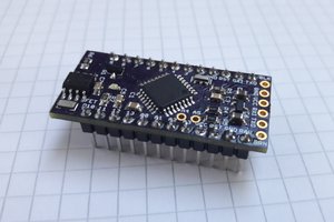
 Max.K
Max.K
 Vishnu Mohanan