Trial assembly
I started by obtaining all the basic components and plugging them together. The Arduino design concept makes it really easy to build up a fairly complex design without any soldering, and it should just work. So I was hoping that this would prove to be the case!
The Grove starter kit consists of several useful parts and an interface shield to connect them all together. I wanted to use several of these components, including the 16x2 LCD, which has a nice RGB backlight that I could use to indicate the device status. There is also a touch sensor that I wanted to try out as a button for the user interface.
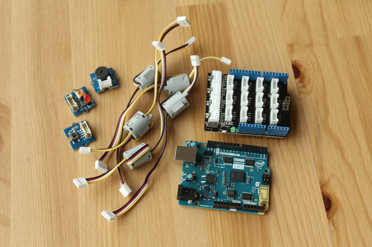
Here is the Arduino 101 with the Grove interface shield and the sounder, LED and pushbutton components, with connecting cables:
And I got this SIM900 shield from ebay - it seems to be a common design:
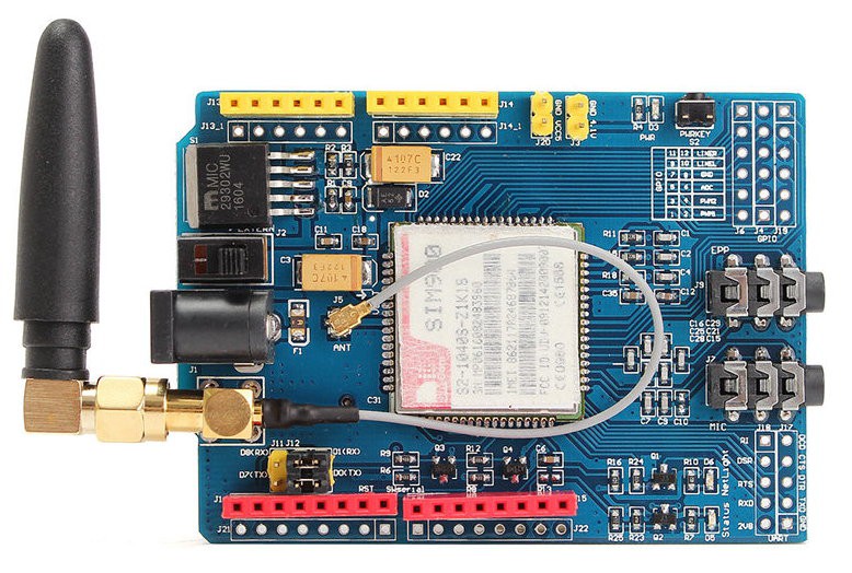
Preparation of the GSM shield
Before using the GSM shield I had to do some preparation of the board, because the pin headers were not fitted. I decided to populate just the pins that were needed. After reading up about the Arduino serial interface, I discovered that the Arduino 101 has two hardware serial interfaces, and the one used for programming is different from the one available on D0/D1, so there is no conflict. I decided therefore to use D0/D1 for the GSM shield, and avoid software serial, which apparently can sometimes be problematic.
In addition to D0/D1 for the serial pins. D9 is used to power the shield on. I found that my board had an open jumper on the board that I needed to solder to connect this D9 line. In the image above it's visible just above the last two pins on the right of the row of red pin headers.
To allow things to fit together better, I relocated the block of serial selection jumpers from the top to the bottom of the board.
Stacking the boards
The GSM shield had to go on top of the stack of boards, as it doesn't carry the IIC pins that are needed for the interface shield. I decided to attach the 16x2 LCD and touch sensor on top of the GSM shield, to make a compact block. The LCD fitted neatly once the serial jumpers on the GSM shield had been relocated. To attach the parts I used hot melt glue and some small balsa wood standoffs. In between the LCD and GSM shield is a piece of rubber sheet to prevent any short circuits between the boards.
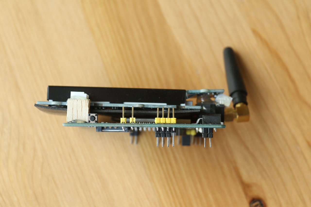
Here is the GSM shield with the LCD and touch sensor firmly attached:
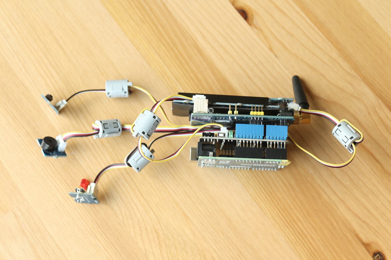
Finally, here is the complete stack, consisting of Arduino, Grove interface, GSM shield, LCD, touch sensor, pushbutton, LED and sounder. For a portable device it is looking rather tall:
The next step was to connect the power, install the Arduino IDE and start writing some software!
Discussions
Become a Hackaday.io Member
Create an account to leave a comment. Already have an account? Log In.