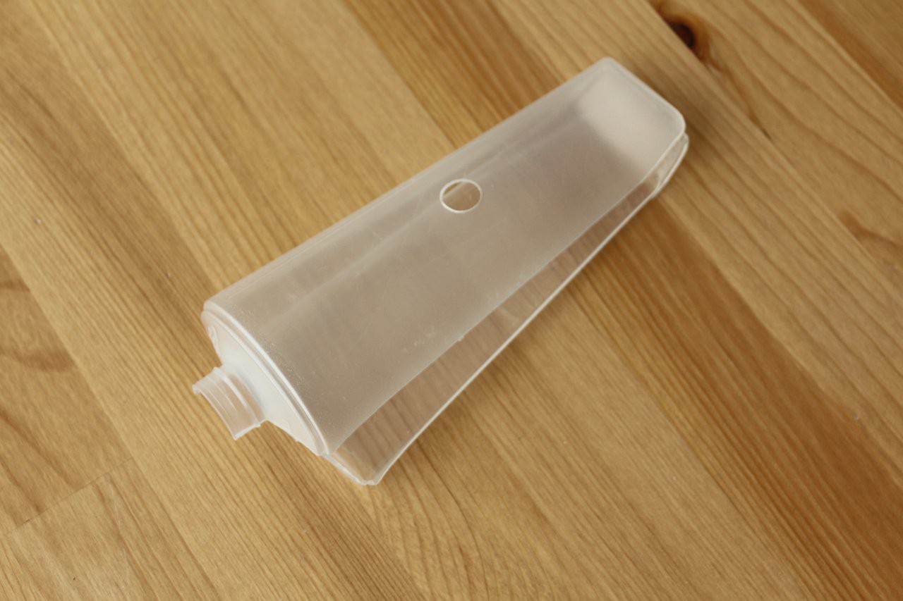
I found a suitable housing for the device, which is an optimum size to hold all the components and has rounded edges suitable for a wearable device. It also has a pleasant scent of mint and tea tree and it looks like this:

As a bonus it came with some free shower gel inside! I used that up first before continuing. Then I cut the housing in half and added cutouts for the LCD and touch sensor. The panic button will fit into the opening where the cap was:
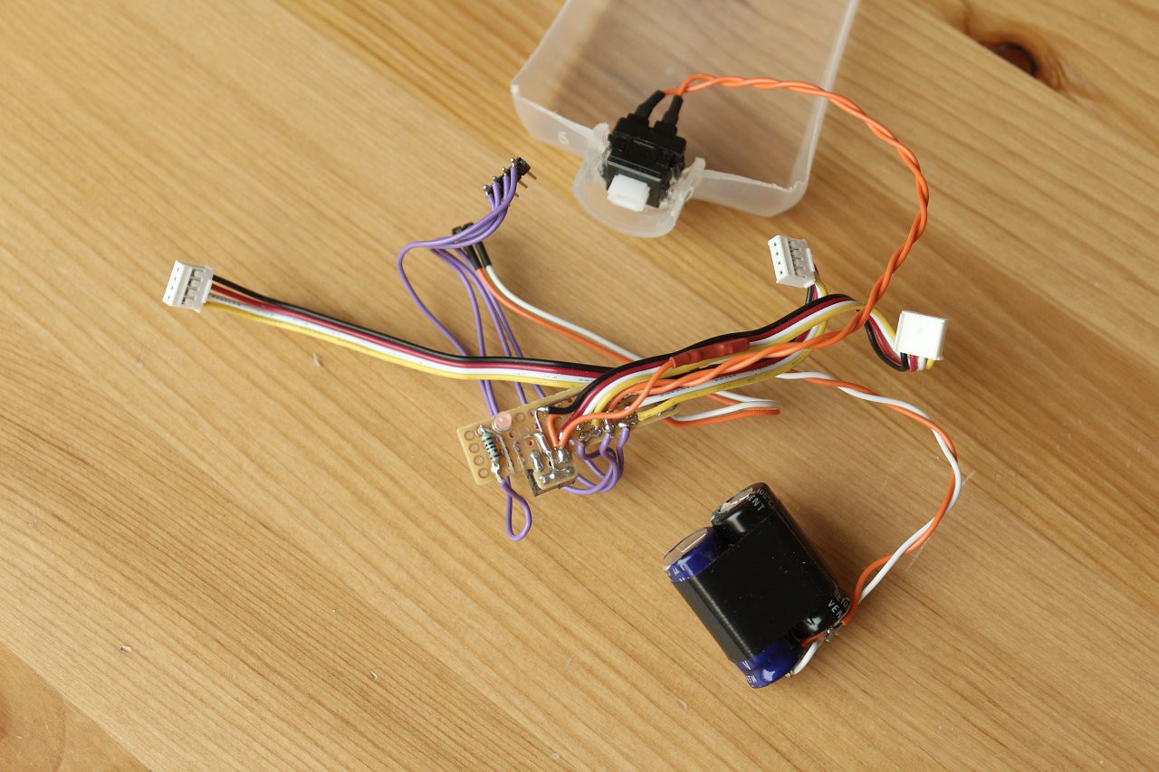
The stack of boards was really too large to fit, so I decided to eliminate the Grove interface shield, which was just connecting bits together. I used a small piece of matrix board as a replacement, with flying leads to plug into the Arduino headers. This board includes the LED, the capacitance for the GSM board power (two electrolytic capacitors in parallel) and the wiring to the panic button, as well as the connectors for the LCD, touch sensor and sounder. Here it is, with the panic button attached and glued into the housing:
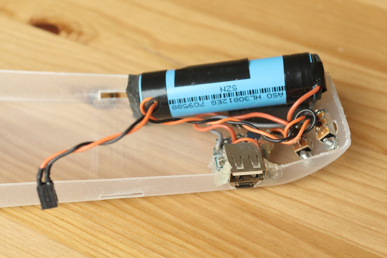
Here are the internals of the power bank fitted into the housing. I added two switches - one to disconnect the cell, and one to switch the device on and off. The power bank circuit has a push button to activate it, and this protrudes from the bottom of the housing. The USB connectors are accessible at the side, to allow the device to be charged up.
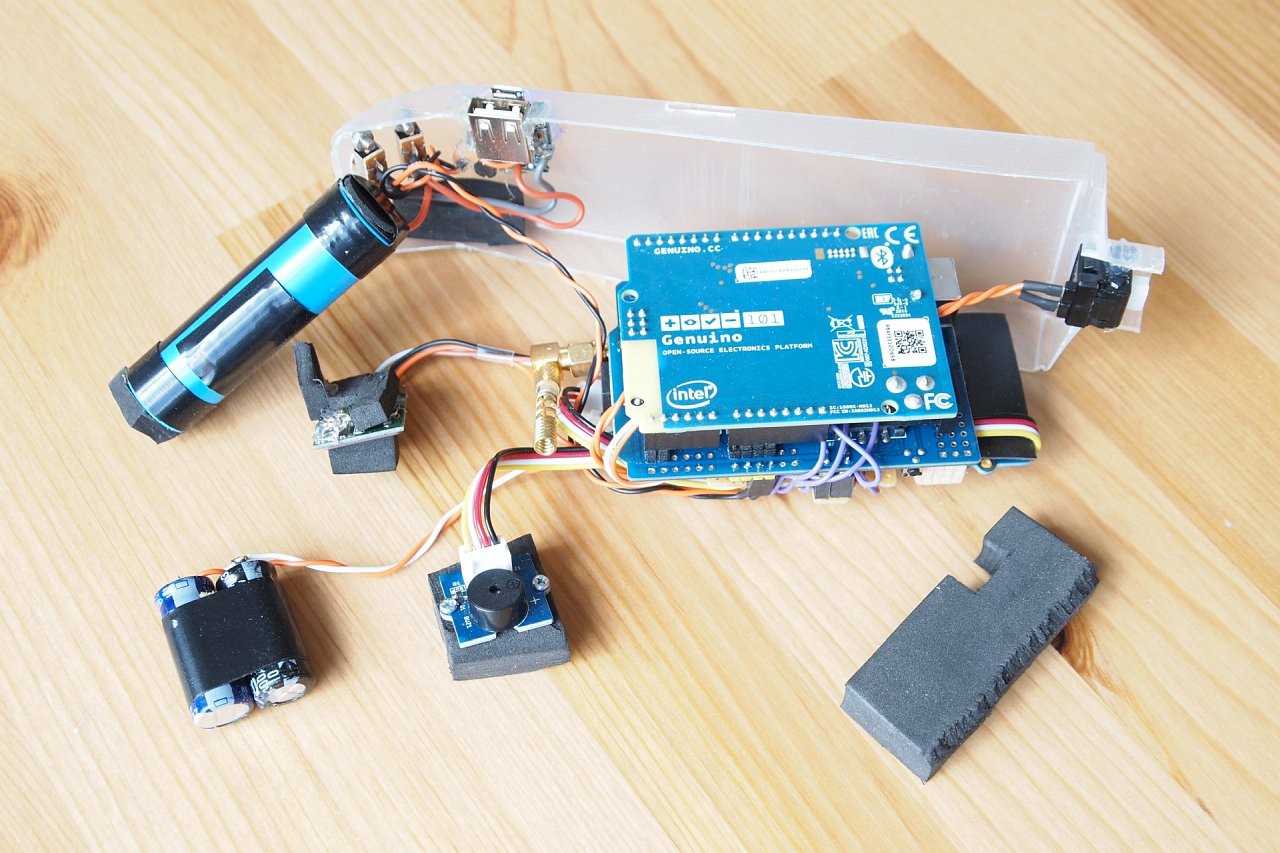
Here is the newly slimmed-down stack of boards connected up and ready to fit into the housing, with some pieces of foam rubber to allow a snug fit:
Now everything is in place - to get the GSM antenna to fit I removed the plastic cover:
And finally with the lid on, held in place with velcro straps that double as attachment straps for wearing the device:
And a view underneath:
Everything fits surprisingly well! To wear the device, it can be attached to the upper arm, like this:
Alternatively, the housing is slim enough for the device to go into a trouser pocket, and this is a bit less intrusive. The fall detection works with the device in either location.
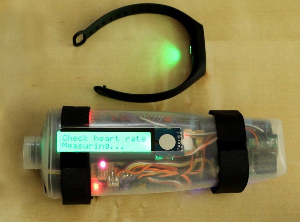
Now everything is in place, and all that remains is to fine-tune the software and try to figure out the BLE heartrate measurement, or get a different heart rate monitor! Here is the M2 strap making a measurement triggered by the device via BLE - if only I could read the result:
Discussions
Become a Hackaday.io Member
Create an account to leave a comment. Already have an account? Log In.