Close
0%
0%

Ankle Booster

A hardware device that attaches to lower legs to increase running performance by boosting ankle propulsion movements.

Similar projects worth following
Building a full body exoskeleton to assist individuals with disabilities or boost performance is a challenging task: I find the major obstacle is the solutions available to implement artificial muscles: devices that generate linear mechanical work out of other forms of energy, preferably electrical. We do have actuators, but a muscle is a lot more than that: it can both move fast and slow, while delivering variable levels of force. An actuator can't do both, and the other available solutions have other limitations.
I decided to start with one step at a time, and for this project the purpose is to build a device that mainly contracts and pulls the heel up in a coordinated way with the ankle movements while running. This approach can help improve speed and endurance while running.

One of my previous project entries, the #Exoskeleton, proposes a full body external suit to improve mobility both for those that lack it and for those that want more. But to get there, several lessons need to be learned. For a start I decided to focus on improving simple (but important) human mechanical tasks. One is running, and this is the purpose of this project, to build a device that can be attached to the lower legs and improve running performance (speed or endurance).

Biomechanics of running

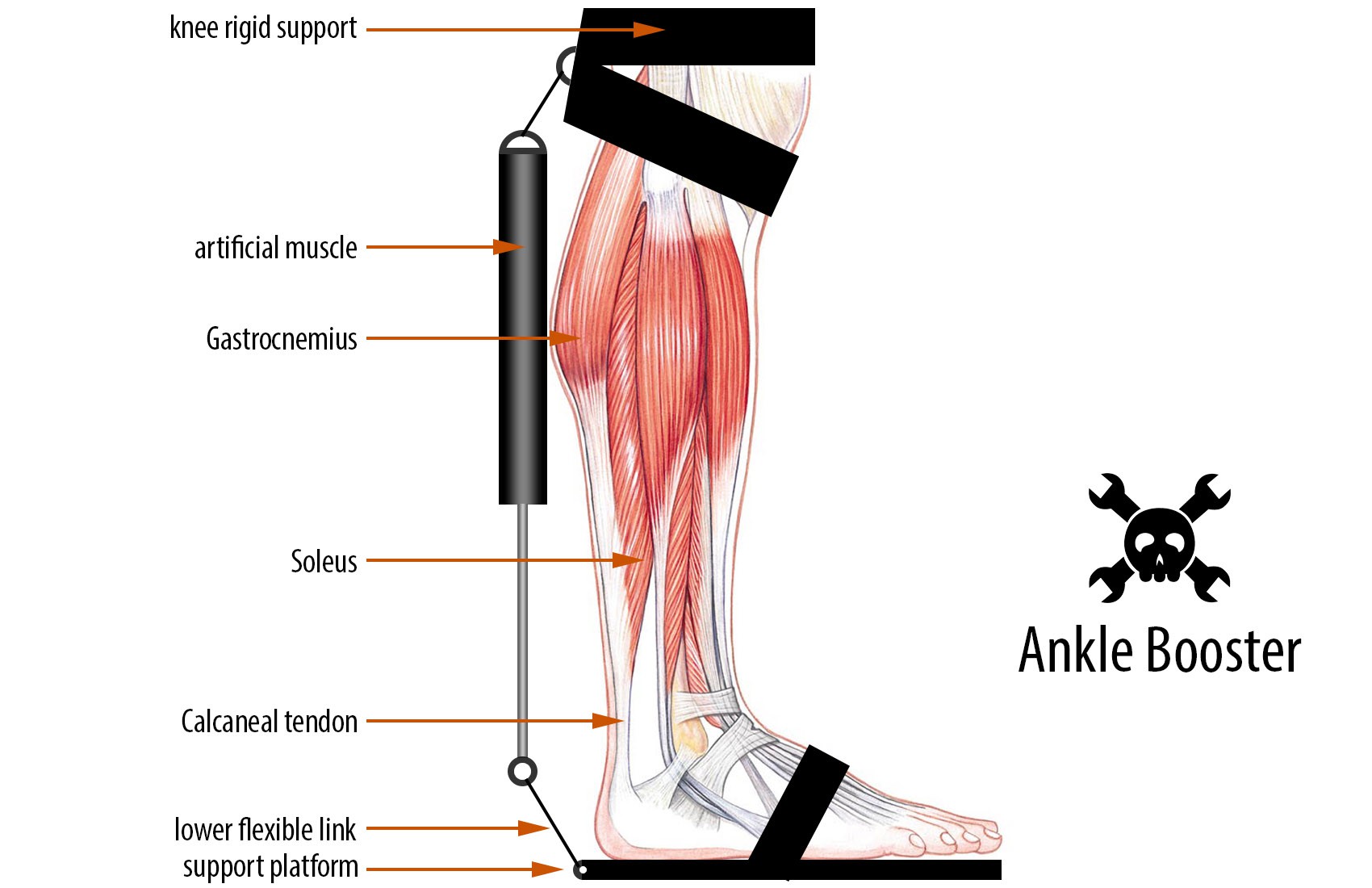
Two muscles have a determinant role in running. First the Soleus accelerates the body forward and upward. Then the quadriceps accelerates the body forward:

Proposed scope

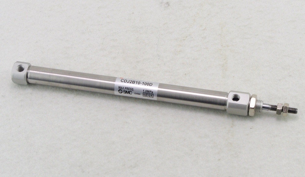
Build a device that can be attached to the lower legs, and assist the Soleus muscle in the ankle movement used for running. It is immediately obvious that a device that contracts is sufficient for this scope.


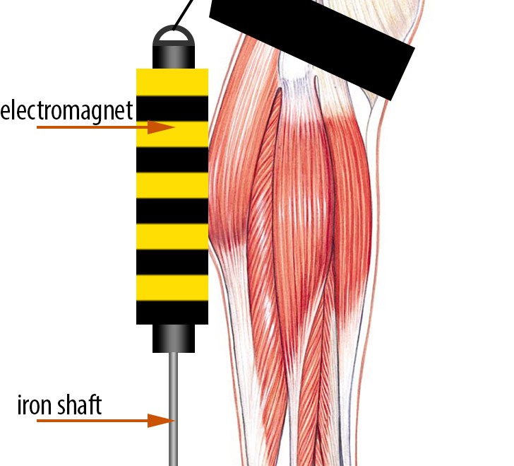
The working principle

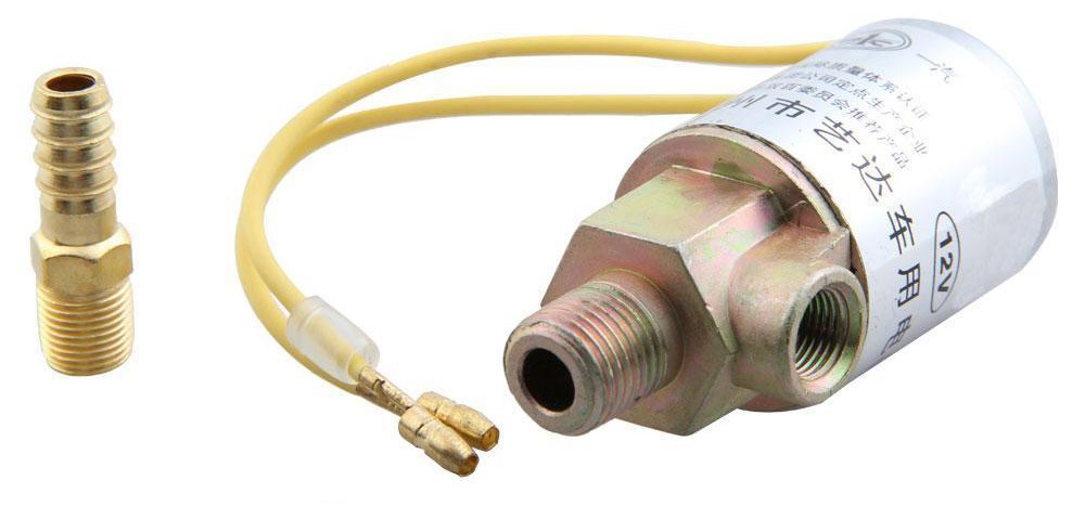
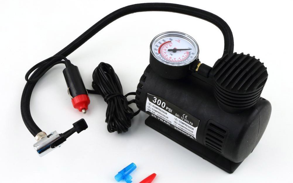
An artificial muscle repeatedly pulls the heel up at precise timing, synchronised with the Soleus muscle contractions. The synchronisation can be triggered by an accelerometer sensor, part of the assembly.

  • 2 × CDJ2B10-100 pneumatic piston
  • 1 × 12V Air compressor
  • 6 × MG995 Servo motors
  • 1 × Electric Winch
  • 1 × Nylon wire

View all 8 components

  • Artificial muscles: the winch

    Radu Motisan09/03/2017 at 23:20 0 comments

    Having little success, despite the many ideas I tried, I decided to check out existing similar technologies to get an idea on what I could try next. I saw a military design and a research university project on assistive technologies in the form of an exoskeleton:


    Looking carefully, it became obvious they both were using a small winch and steel wires to emulate muscles and tendons.

    I had a few unused electrical screwdrivers in my toolbox, perfect for making a DIY winch and keeping size low. The only issue was they had low RPM, and ran on 3.7V. I planned to increase both the speed and the working voltage up to 12V. So I had to rework the motor's windings with thiner wire for more turns and make Ohm's law happy (more turns, more resistance, less current, more voltage).


    The new rotor coils came out nice, with about 40 turns per coil (not enough for 12V, but good for a few tests):


    Load test

    So here's 4L of water (4Kg) in a bucket, connected to the geared motor using a strong nylon wire (to be replaced with steel):

    The diameter of the wire roll could be increased for higher speed.

    This design is probably the best way to go, but I have to build a better winch. However the design is going to be more complicated, since the rotation axis need to be parallel to ground and not perpendicular. It would need to be fixed to the knee rigid support, and it might not be very comfortable. Also 

  • Artificial muscles: electro-magnets

    Radu Motisan09/03/2017 at 22:58 0 comments

    The previous attempt using servos had the advantage of being a direct mechano-electrical converter, meaning the servos would translate the battery energy directly to the needed mechanical linear movement. It would have still been impractical even if it worked, because of the many servos needed. Not exactly a good addon to fit on the lower legs.

    This new idea of using an electromagnet promised a linear design, very similar to a piston. The shaft, made of iron, would be moving up towards the knee rigid support using an electromagnet.


    I based this idea on my previous experience with coilguns. I knew that higher voltage would allow for a longer movement interval, while higher current would increase the kgf applied to the shaft.

    One interesting idea to compensate for the inverse square law of the electromagnetic field was to use multi-stage coils, exactly like in a multistage coilgun design. 

    Unfortunately the generated force was in the order of grams-force. Going up to 10kgf with a 10cm displacement was just a nice dream, totally unsuited for this design.

    Something that might have worked was a combination of an electromagnet and a lever, to translate the strong electromagnetic field right next to the coil into a longer movement interval. Not sure about this, but I'm not very optimistic about it.

  • Artificial muscles: paralleled servos

    Radu Motisan09/03/2017 at 22:48 0 comments

    I was not entirely sad about moving away from pneumatic pistons. Such a setup would make my build too similar to a steampunk design, just imagine the sound of it while running. I'd prefer to lower the noise level if possible. I had several full metal gear servos in my toolbox:


    For instance the MG995 (that I had available) specs show:

    Operating Speed: 0.13sec / 60 degrees (6.0V no load)
    Stall Torque : 15 kg-cm (208.3 oz-in) at 6V

    Definitely promising, considering my idea was to use 6 in parallel.


    However the tests came out bad: the entire setup had very little power, making it unusable for the project's purpose. Probably better servos could still have this, but I don't have other models to try.

    Time to try something else.

  • Artificial muscles: the pneumatic pistons

    Radu Motisan09/03/2017 at 22:29 0 comments

    Pneumatic pistons are mechanical devices which use the power of compressed gas to produce a force in a reciprocating linear motion. You can see an example below:

    For the purpose of this project, we are only interested in the contracting effect. These were my immediate choice for the first tests. I sourced several sizes, thinking I will be able to integrate them with various body muscles. For the ankle, I opted for the CDJ2B10-100, with double acting and a  10-100mm shaft movement interval:

    These are rated for max pressure of 1.5MPa and have a piston speed of 50-750mm/sec, making them suitable for the project's purpose. 

    Pneumatic artificial muscles, while lightweight and inexpensive, pose difficult control problems. To make them work I needed compressed air, pneumatic hoses and electromechanical valves, not exactly compact hardware.

    I needed solenoid valves to control the air flow going into this piston. The air needs to be rushed in and out periodically, to keep paste to user's movements. The electro-valves where 12V heavy duty variants, stressing the heavy part of the word:

    The entire system was thought of operating on 3S Lithium batteries, for about 12V of nominal voltage.

    The compressed air source was a portable auto car electric air compressor, of max 300PSI used to inflate tires:

    And finally, besides the various connectors and accessories, the pneumatic hose used:

    The first tests

    All I had to do was to power the air compressor using a 3S battery, and connect it to the pneumatic piston. The results where good, and it appeared promising.

    Load tests

    I need about 10kgf per leg and considering the running speed, a piston operational frequency of at least 1Hz. So what I did was to put about 2L of water (2kg) in a plastic container, and hook it up to the piston to test the contracting movement:

    Results? The setup failed to raise the load which remained stuck at ground level.

    Conclusion

    While this approach certainly has the potential, I didn't use the right components, proper pistons and a proper compressed air source. To simplify the design, it is possible to use a container with compressed air and drop the electric air compressor. Nevertheless, bigger pistons and higher pressure is needed to achieve the desired results. I decided to look for alternatives (available in my toolbox)

View all 4 project logs

Enjoy this project?

Share

Discussions

mael wrote 09/20/2022 at 22:42 point

hey i was wondering if this is still ongoing 

  Are you sure? yes | no

Similar Projects

Does this project spark your interest?

Become a member to follow this project and never miss any updates