 Bert van den Berg
On power up the SiLabs C8051F380 main micro communicates over two lines with the ATMEGA micro which opens up a text file on the SD card which contains instructions as to how the data logger is to operate.
The file contains information on what phone number(s) to send text messages to, the rules about when to send text messages (truck speeding , battery needs charging, etc.) and a unique 64 character truck ID descriptor.
Data logged is GPS time, position, speed, bearing, date, raw 3D accelerometer and gyro data, outside air temperature, truck CAN bus data, wind speed/direction and spares for future update (humidity, barometric pressure, etc.). A Bluetooth dongle is connected to the vehicle's OBDII connector and CAN bus data is extracted from the vehicle via Bluetooth. On average one "record" of 256 bytes of data is save to the 64Mbit flash memory every 1.3 seconds in ASCII comma delimited CSV format. This format allows for easy import to EXCEL or viewing with any text editor.
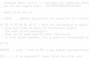
A sample of one 256 byte record of data:
021207,3542.3160,17417.7103,000.30,307.01,140817,-00415, 00151, 00089,-00056, 00050,-00007, 023.87,0000,00000,000,0000,011.23,070,0000000000000000000000000000000000000000000000000000000000000000000000000000000000000000000000000000000000000000000000000000 <--- (note - CAN bus data not being recorded yet, in progress)
When 512 records have been saved to the flash memory (approximately 11 minutes worth), the data is sent to the ATMEGA micro-controller which in turn saves it to a FAT32 format text file with a file name that specifies the date/time the file is created, vehicle ID and trip number. Data is appended once every 11 minutes until the date changes and the file name changes.
Whenever the vehicle stops for more than the specified amount of time (specified in the instruction file - 30 seconds or so) the logger tries to contact the base station via the 2.4Ghz radio transceiver. If it is able to connect all the data from the flash memory (a maximum of about 10 hours worth) is sent to the base station and the flash memory is erased. The 32GB SD card files are never erased and can hold over 5 years of data.
To save power the main micro has the ability to switch ON or OFF most of the subsystems such as the GPS, 2.4Ghz radio transceiver, etc. Power is applied to each individual subsystem only when required.
When the vehicle stops moving for more than a specified amount of time (30 minutes or so), the main micro shuts off power to all the subsystems except the real-time-clock chip and the 3D accelerometer/Gyro. The main micro switches itself into a low power mode by using a lower clock frequency. This saves battery power. The main micro monitors the the 3D accelerometer/gyro to detect when the vehicle has started to move again and powers up the required subsystems (GPS, wind sensor, etc.).
The code in the C8051F380 main micro controller is written in a mix of C and 8051 assembly using the Raisonance RIDE C compiler/assembler. The program is flashed into the C8051F380 using the SiLabs Integrated Development Environment (IDE) software.
 Yann Guidon / YGDES
 Elbert