 ajlitt
The boards came in today, so naturally I had to get soldering despite being tired from working late last night.
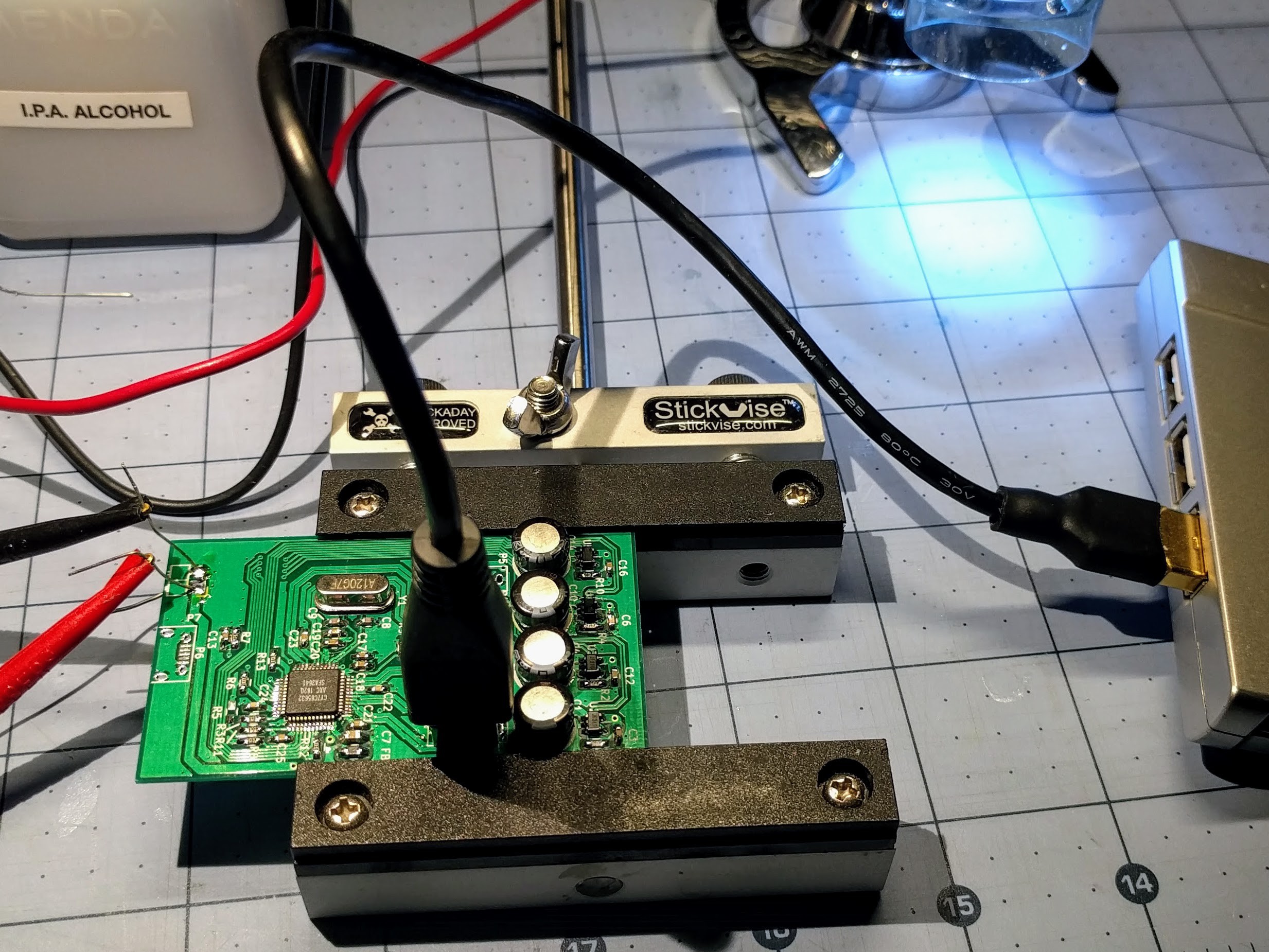
I populated everything but the USB power jack and the four downstream node USB plugs. I didn't want to waste the connectors until I checked out the upstream end of the hub.
I first smoke tested the board with my bench PSU and checked that the oscillator was doing its thing. Once satisfied that I didn't have any surprise dead shorts, I hooked it to my PC through a micro USB jack to USB-A plug cable going to an intermediate sacrificial hub. I was able to see the hub enumerate under Linux, and checked that it's reporting as having per-port power control.
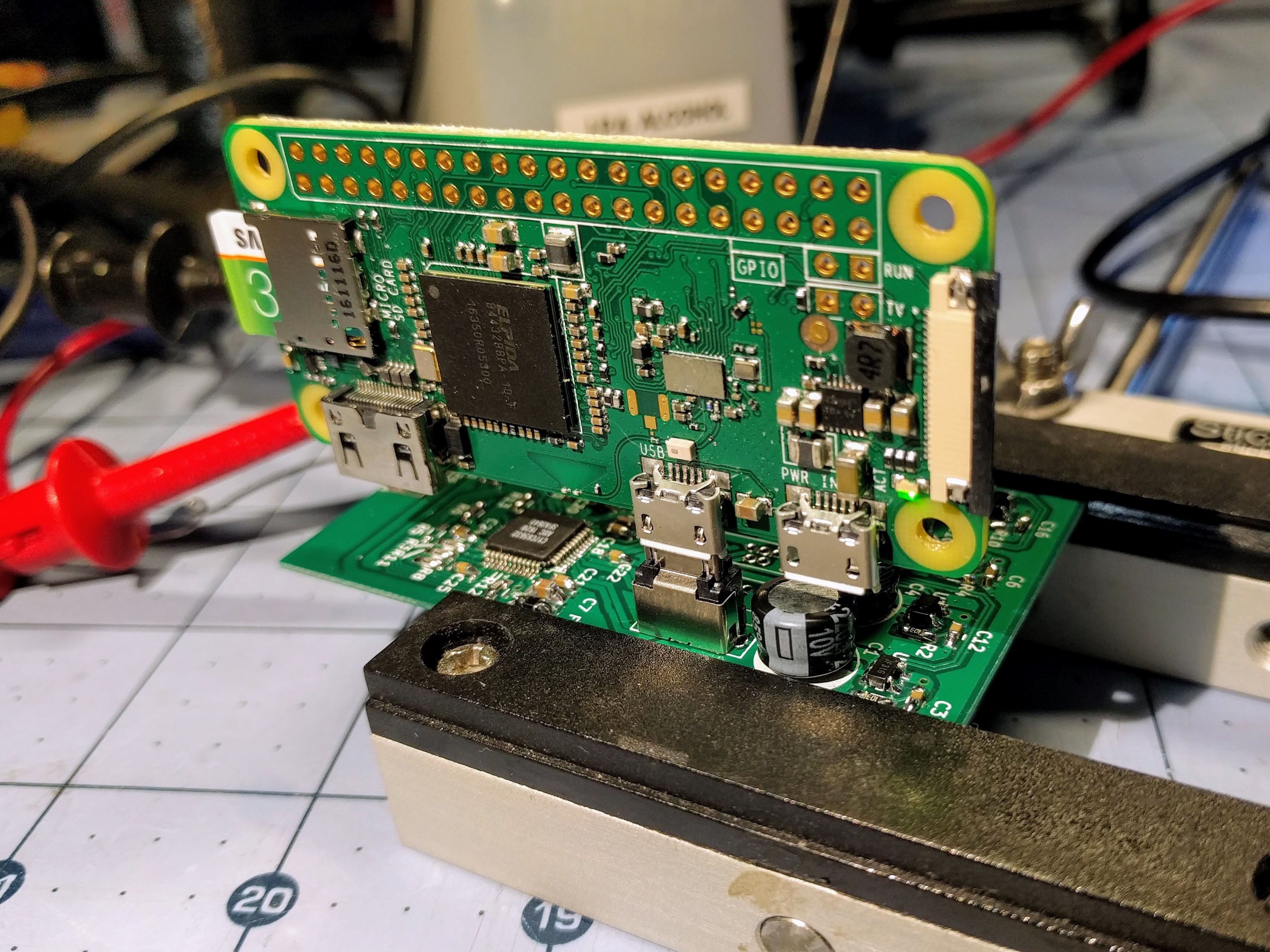
I also did a test fit of a Pi Zero W, and since I'm now confident it's not going to do any damage I powered it up. The Pi's LED did its blinking thing as usual as Linux boots.
Stuff I learned:
- The hole dimensions for the USB vertical plug are too big to fit snugly. I had to "justify" the upstream plug with one edge of the board. I'll need to remember to align the other four the same way to keep the Zeros spaced uniformly.
- The Cypress hub IC shuts off the 12MHz oscillator when nothing interesting is happening, probably to save power. I didn't catch this detail in the datasheet. I spent a good half hour wondering why I'd see a fleeting 12MHz on the scope on power-on and nothing afterwards. I suspect it will stay on once I get downstream devices connected.
- My thermal reliefs aren't that relieving. I soldered in one of the electrolytics backwards, and it was a pain to desolder and clean the hole on the grounded leg. I should have used thinner spokes on the reliefs, and made sure that there was no additional ground traces hiding under the plane fill. It would also help if I replaced the solder sucker I broke a few years ago.
- Just because silkscreen art looks good in the KiCAD 3d render doesn't mean it will look the same on a finished board. For grins I converted a photo of a picture one of my kids drew in school to a KiCAD symbol. What was supposed to be a skull looks more like an upside down diseased pear. Elecrow and other PCB manufacturers have a resolution limit to their silkscreen.
Next I need to get the rest of the connectors in, test downstream power control, make up a test cable for the downstream ports (more later), and maybe plug in some more Zeros. But that will have to wait for the weekend.
Discussions
Become a Hackaday.io Member
Create an account to leave a comment. Already have an account? Log In.