 jean.perardel
As I was saying in a previous post, I bought some CIS sensors on Ebay.
I have already hacked several sensors I found directly in old scanners, but this method is really time consuming... and you never really know what kind of sensors you will find!
So I wanted to find a more "generic" CIS sensor, and this wasn't easy... I ended up buying on Ebay some sensors with the wrong references and no datasheet.
When I received them, it was the start of a very long day...
I started with some internet research, all the videos and blogs with people playing with CIS sensors (on their oscilloscopes most of the time). I couldn't find any information about those references.
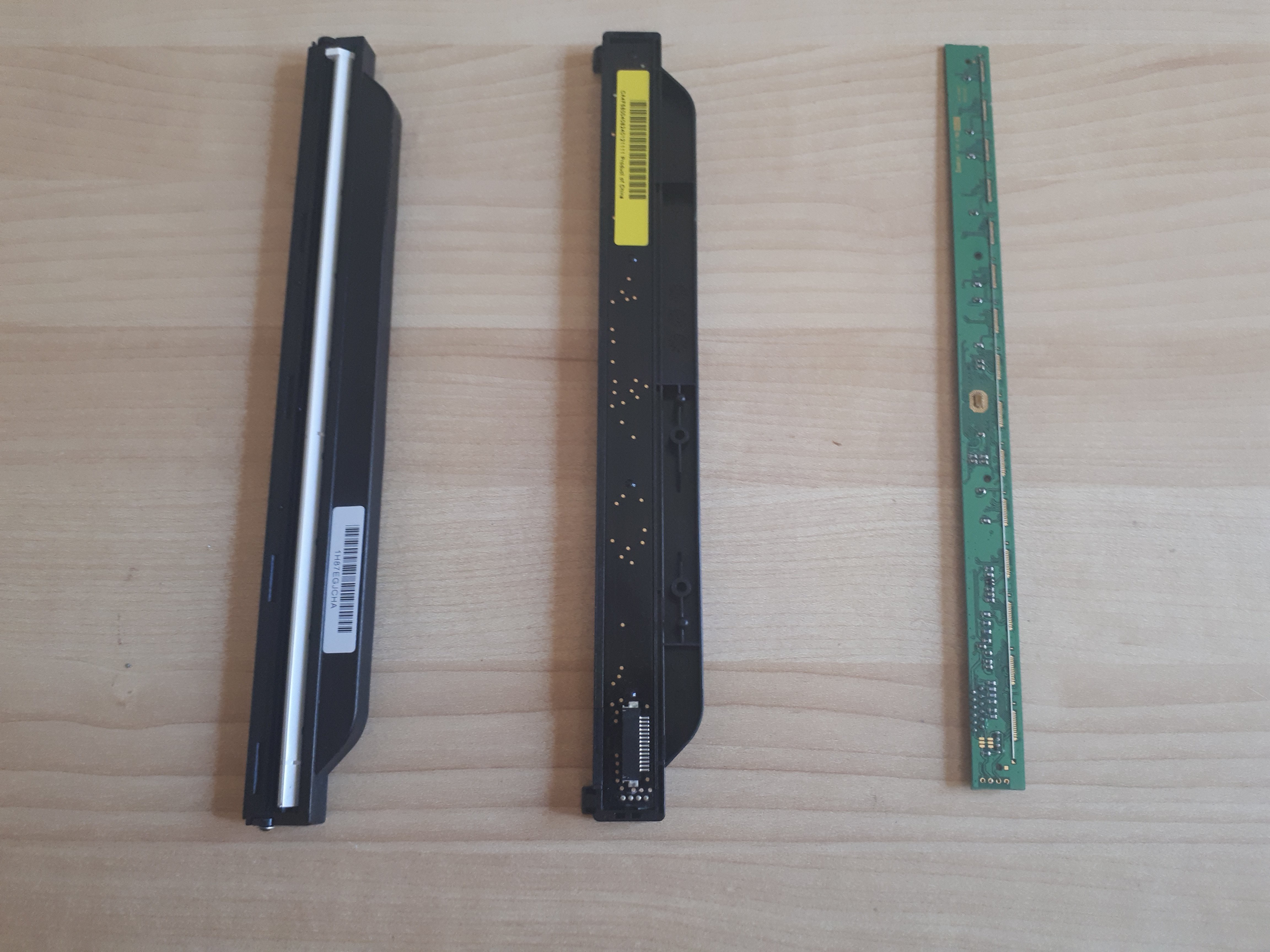
From left to right : CIS front sensor with a cover, CIS back sensor with a cover, CIS front sensor without a cover
I started with the CB376-67901. I bought two of them, so I removed the circuit of the first one to have a better visual access to the lines. This sensor has 14 lines and you need a flat flex scanner cable (you find some in every scanner) and a ZIF connector to build an interface board more easily.
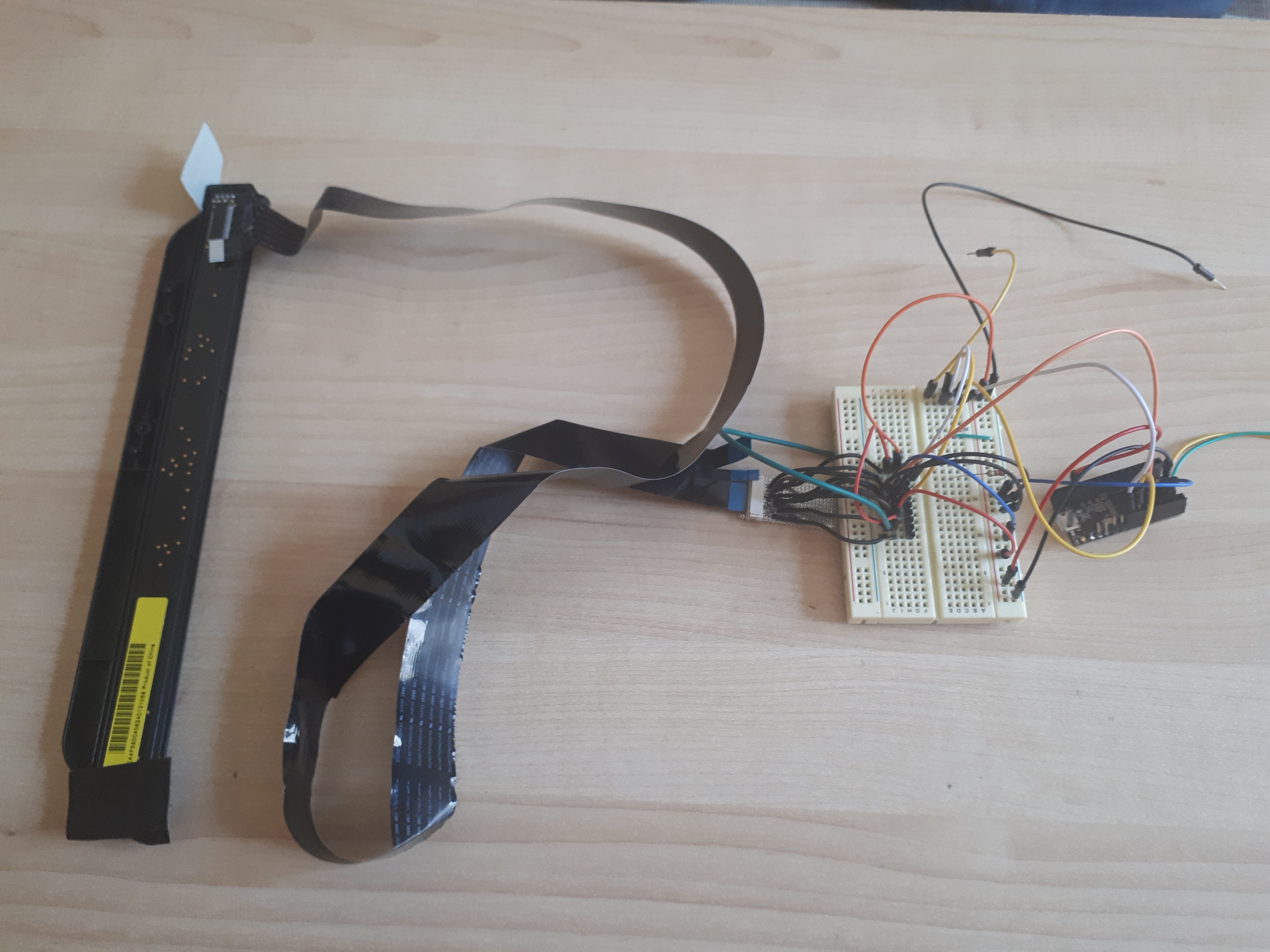
From left to right : CIS sensor, Flex cable, ZIF connector interface board, breadboard interface, Teensy 3.2.
I was able to identify :
- GND on Pin 6 and 8,
- LED pins on Pin 11 to 14
- VCC on Pin 2 and 10.
That's a good start, but still 6 Pin left for the :
- Analog output
- Clock
- Latch
- Differential lines?
- Maybe others if the protocol is different...
Then, I compared them with some CIS I used to hack and I discovered that CIS from the brand HP had the same Pin so far. Interesting! But at that time (2 years ago!) I couldn't make it work... Here is the informations I had :
- Analog output on Pin 1
- Latch on Pin 5
- Clock on Pin 9
- Still no idea for the other lines
Second step, I found an old HP scanner and opened it. And this was an amazing moment : the same plastic package, and it looked as throught it was the same Pin from the one I had so far!!
So I wired my CB376 CIS sensor directly into the flex connector of the mother board, and I could see the outputs of the CIS on line 1.
Here is the exact configuration :
- 1 Analog output
- 2 VCC (5 volts, but works with 3.3)
- 3 VCC 3.3 volts
- 4 GND
- 5 Latch
- 6 GND
- 7 differential signal (opposite to the clock)
- 8 GND
- 9 Clock
- 10 VCC
- 11 - 14 RGB LED
A few lines of code on the Teensy board, and now you have a new sensor to play with!!
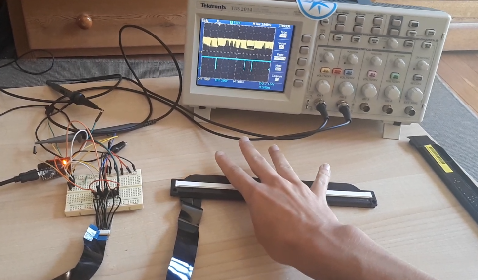
The blue signal is the Latch (to help to synchronize), the yellow signal is the analog output. You can see 4 rounded peaks very close to each other, on the yellow signal, it's my 4 fingers. ^^ I ll upload a video soon!
I actually damaged one one of the two CB376, some pixels don't work anymore... But I still have one more sensor, and also the possibility to order more!
I haven't yet succeed at hacking the CE-841. Here is what I can say about it so far :
- 2 GND
- 5 GND
- 8 GND
- 14 LED
I need to work a bit more on this. I ll keep you posted! ;-)
Discussions
Become a Hackaday.io Member
Create an account to leave a comment. Already have an account? Log In.
Did you ever persue any further tests with the Q8100-60002? It's the only cheap, abundant and 2400dpi* sensor I can find.
*Looked at all the compatible printers and they all specify 2400dpi optical resolution.
Are you sure? yes | no
Thanks for your time and devotion to this. Did you end up having any luck with the CE841? These seem to run at about 30% of the cost of the CB376. I'm looking at making my own project based on these sensors but the complete lack of technical data (either from the printer vendors in the form of schematics or the manufacturers of the sensors themselves) is leaving me in complete frustration. I don't have a scope to mess with them. I tried a sensor I pulled from a random Epson MFC but having limited to no luck with it. My problem is that I am unsure if the sensor will work for my needs (and I need two identical ones for my project) so not wanting to fork out the inflated price for the CB376 as it may not work, so finding a cheaper sensor would be good for me. There is also the crazy cheap Q8100-60002 but that is 14 pin so possibly uses LVD.
Are you sure? yes | no
I'm looking to use the Q8100-60002 for one of my projects. I also lack a scope so I'm not sure what I'll do when I get to that point.
Are you sure? yes | no
I bought a few of the Q8100-60002 and they seem identical to the CB376 above. Although, the Q8100 is supposed to suit a Photosmart C4180 (which I managed to acquire), the ones i got do not work in the printer - The image comes up all gabled.
The good news is that i have had at least SOME success with it but I only seem to be able to read about 1/5 of the sensor (if that). I have not touched it in a few weeks but it does seem that you need the differential signal on pin 7. I don't think the 'shift' is working properly for me.
I have been using a logic analyzer to read the signal from the printer and re-create that with an ESP32 but I think the ESP32 is too slow to create a good enough signal for the inverted signal. I have purchased an inverting buffer to try but not yet had a chance.
For my intended application, I'm not convinced I can get it to read fast enough but its still on the todo list to get it working.
Are you sure? yes | no
Nice to know that any data at all can be obtained from these cheap sensors. Could you tell me what the PCB dimensions are (L*W*H) and if it can be removed from the plastic housing?
Are you sure? yes | no
It can be done but I'd strongly advise against removing it from the holder. The wires to the ICs on the board are microscopic and exposed. You will snap them from simply touching them. It also has a fine light filter to ensure linear/parallel detection of light. The board dimensions are about 13x231mm
Are you sure? yes | no
This Eureca.de site has some Contact Image Sensor modules and industrial line scan cameras with high scan rates. https://www.eureca.de/27-1-CMOS-Sensor-Inc.html
I also considered seeing what it would cost to make a PCB with the sensors laid out to order from smaller diode arrays. If you are interested I will look more.
Are you sure? yes | no
That Weihai Hualing list mentions CameraLink. The specification is at https://en.wikipedia.org/wiki/Camera_Link I expect to see twisted pair differential signals more and more. Low Voltage Differential Signaling. I think it better to buy new and future CIS and learn them, than to spend time on obsolete and undocumented.
The CIS market is growing. Here is a note about that that also lists the key manufacturers. I contacted Mitsubishi Electric but their manager is out of town. https://www.wboc.com/story/44166889/contact-image-sensor-market-size-is-expected-to-grow-at-a-cagr-of-68nbspduring-2021-2026-with-top-countries-data
Mitsubishi Electric
Canon
ROHM Semiconductor
ON Semiconductor
Syscan
Lite-On Semiconductor
WHEC
CMOS Sensor Inc.
Tichawa Vision
Here are the ROHM sensors - https://dtsheet.com/doc/1727125/contact-image-sensor They say single channel analog out. So there are LOTS of fast ADC interfaces that can be used. Sounds like you are already familiar with some of that. I like SDR methods because of the active community and the FFT tools. These are analog signals ultimately
Are you sure? yes | no
I found that the Brother DS520 is TWAIN/WIA and so is that MUNBYN. If we can find ways to use them that way, it would be nice, but everyone seems to make their own version, so better to talk to the sensors directly, write the interface then make applications on top of that. Java might be worth looking at. I mostly use Javascript (have done a lot of camera and microphone work), but also VB.net and a bit of Visual Studio C and Visual Studio Code. If you can get the raw data onto a disk that linux can see, it is not hard to read it. NodeJs can watch a directory for new files. Or just store them in a known format and process later. Not sure what you are trying to do with these. Kind of tired.
Are you sure? yes | no
I am looking for ways to talk to the CIS sensors so I can read them at maximum line scan rates. In these descriptions, you will find rates in kHz (thousands of scan lines per second) or in microseconds per line. I will buy you some CIS sensors, if you can help me get data from them. I want to see if they are picking up magnetic noise. So I am looking for more bits per color and faster lines per seconds (to improve statistics). I want to run them for days at a time, no illumination, or as close to uniform and stable illumination as possible. I have windows and linux. I have Raspberry Pi, Jetson nano, arduino, ESP32. Have oscilloscope but my eyes are getting too bad for small work. Programming and statistics for more than 50 years. If you need something ask. If you can find any CIS with real documentation, it is easier to buy than spend time hacking to save a few dollars. If we work together we might find it easier.
Are you sure? yes | no
Weihai Hualing OptoElectronics offers CIS. Their CIS formats are listed at https://www.w-hec.com/en/product/cis-industrial/ and the image of the table is https://www.w-hec.com/whec_wp/wp-content/uploads/2021/03/9972294a72103ce722965c2538d9ff3c.jpg
Are you sure? yes | no
Bought a MUNBYN DS001 that contains lite-semiconductor.com 216 mm (8.5 inch) 900 DPI sensor. lite-semi bought out by Diodes.com Plano TX. The list of CIS formats from Diodes.com is at http://www.liteon-semi.com/upfiles/CIS/cis%20product%20list%20eng.jpg
Are you sure? yes | no
hi,I have a color scanner project, can we work with you on this? The scanner will scan in color. it will be like sean hodgins' image sensor or a4 scanner. tubbiya@hotmail.com or WhatsApp +905327099681
Are you sure? yes | no