 visualkev
A place for everything and everything in its place - All components are mounted and/ or wired up. everything connected to the terminal block in the lower right is part of the 12 volt circuit that the relays will be switching on to eventually light pyros. The 5 cell AA battery pack in the lower left powers the control logic - purple pcb center and relay coils.
This is the rear of the chassis showing the poorly cut wire access slots, the ground bus and the antenna.
Here is the front panel with the master power switch in the center, 12volt charge socket to the lower right and the buzzer hole to the left
The enclosure/drawer closed up. Next step: test that it all still works.
P.S. Please disregard the mess caught in the shot.


 J3TTBlack88
 zacnotes
 Frank Buss
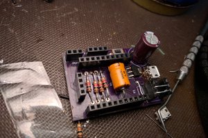
 Alan Rager