0%
0%
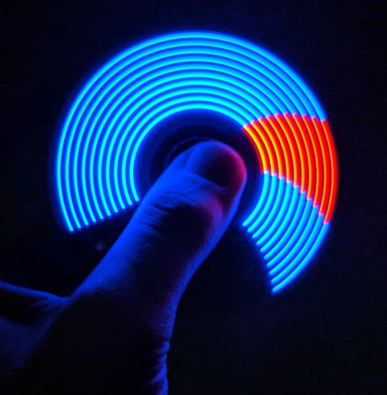
Spinduino
IoT Fidget Spinner with Bluetooth Low Energy and POV LED Display
 Uri Shaked
Become a Hackaday.io member
Already have an account? Log in.
Just one more thing
To make the experience fit your profile, pick a username and tell us what interests you.
Pick an awesome username
hackaday.io/
Your profile's URL: hackaday.io/username. Max 25 alphanumeric characters.
Pick a few interests
Projects that share your interests
People that share your interests

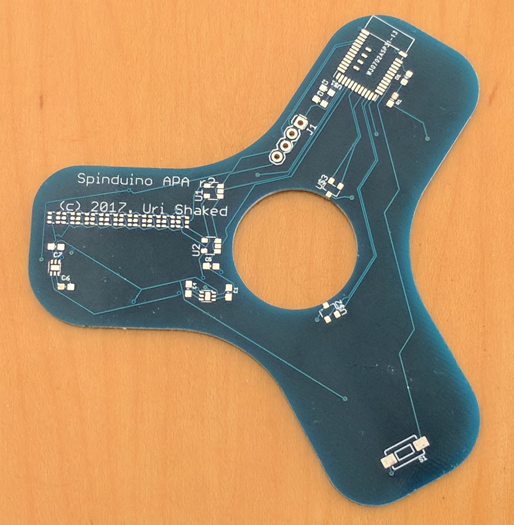 Soldering the PCB and trying to run it revealed some issues with the new version. The most prominent one was switching the Enable and Flying Capacitor pins of the 5V Charge pump (TPS60150), which basically rendered it useless, as it was feeding the LEDs around 2.5V instead of 5V. Also, pouring copper below the antenna of the BLE module was not a good idea, as it reduces its performance. I also used the wrong footprint for the Logic Level converter (MC74VHC1GT125), so I had a hard time soldering it.
 Benjamin Broce
 Max.K
Max.K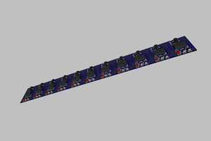
 FuzzyNoodle
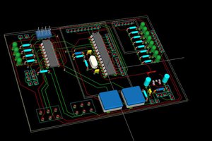
 Michael O'Toole