The device is designed to be as small and lightweight as possible. This also allows this module to be mounted on a wide variety of different stuff for measurements.
Using the device:
Turn on the switch (button should be on the "outside"). The device is now active.
When pushing the red button, the LED shines and a measurement cycle begins. The device will now save a measurement point every 1ms until the storage is full (after about 12sec) or the button is pressed again. A measurement cycle is finished, when the LED turnes off.
Keep the device turned on. Turning it off will delete the saved measurement.
Pushing the button again will start a new cycle and overrides all existing data.
Connect the device via micro USB (every phone charging cable can be used) to your pc and start the GUI. Select the COM-port of the device (most likely something above com3) and klick connect. The data of the last measurement can now be read out and visualized by klicking the "read" button, and be saved in an .txt file with the savebutton for further investigation/calculation in matlab.
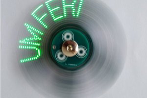
Here is an example of how is may look like on a pendulum:
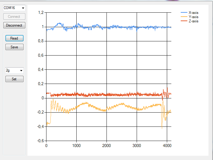
The device can stay plugged in for further emasurements and will always charge up when connected.
The Battery is automatically charged whenever the device is plugged into the USB port.

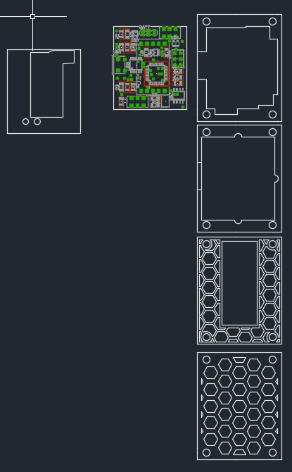
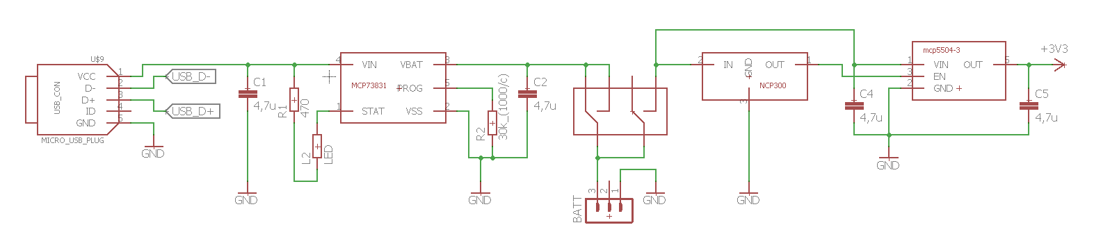
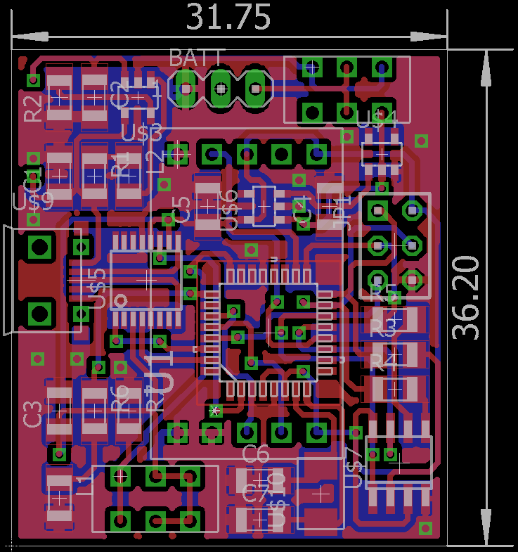 The design was meant to be as compact as possible. As well as being able to be soldered by hand.

 Matej Nogić
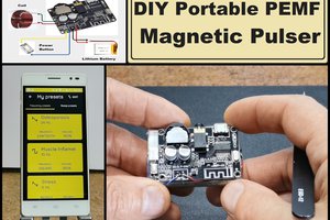
 mircemk
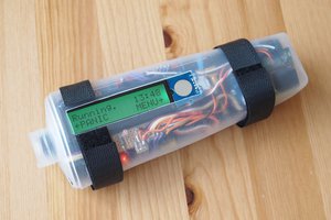

 Joseph Primmer
Hey,
First of all, it’s a just awesome project :D BUT …. I found more compact and simpler one here: https://www.tindie.com/products/11072/
It good If you don’t want to bother soldering any electronics and want SIMPLE PLUG&PLAY like Arduino device.