 deʃhipu
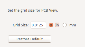
The grid is a very useful tool. It lets you align all your parts properly, and make sure the traces between them are straight. However, the default grid in Fritzing is set to a huge 0.1" — which is probably fine for large through-hole parts, but completely inadequate for the smaller SMD components. Fortunately you can change the grid size using the View → Set Grid Size... menu option:
I usually start with a pretty large grid, such as 0.05", and then halve it whenever I need more detail or denser traces. This lets me make sure that all the large parts are properly aligned to the bigger grid, but the traces can still go around them.
You can also temporarily disable snapping to the grid with the menu option View → Align to Grid, or by holding down the Ctrl key while moving a trace. This can be useful for those few traces that don't want to align no matter what you do, because the footprint you are using is not compatible with the grid you have set.
Another trick is to hold down both Ctrl and Shift keys while moving a trace — then it will automatically snap to horizontal, vertical or diagonal positions. I use that to connect traces to the pins of small integrated circuits, which somehow never align with my grid. So I make the first segment of the track horizontal, until it crosses the grid, and from there it all aligns properly again.
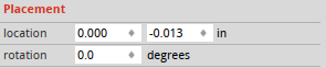
Some objects, like the PCB itself or images, will never snap to the grid for some reason. To align them perfectly, you can use the "location" and "rotation" properties. This is also the way to get a rotation that is not a multiple of 45°.
Discussions
Become a Hackaday.io Member
Create an account to leave a comment. Already have an account? Log In.