 zakqwy
This project is a layout-only exercise, so it starts with the Black Magic Probe Mini v2.1 schematics published in the FAQ section of the project's wiki. After reproducing the schematic in KiCad, the X220's palm rest was measured and test-fitted with a cardboard mockup:
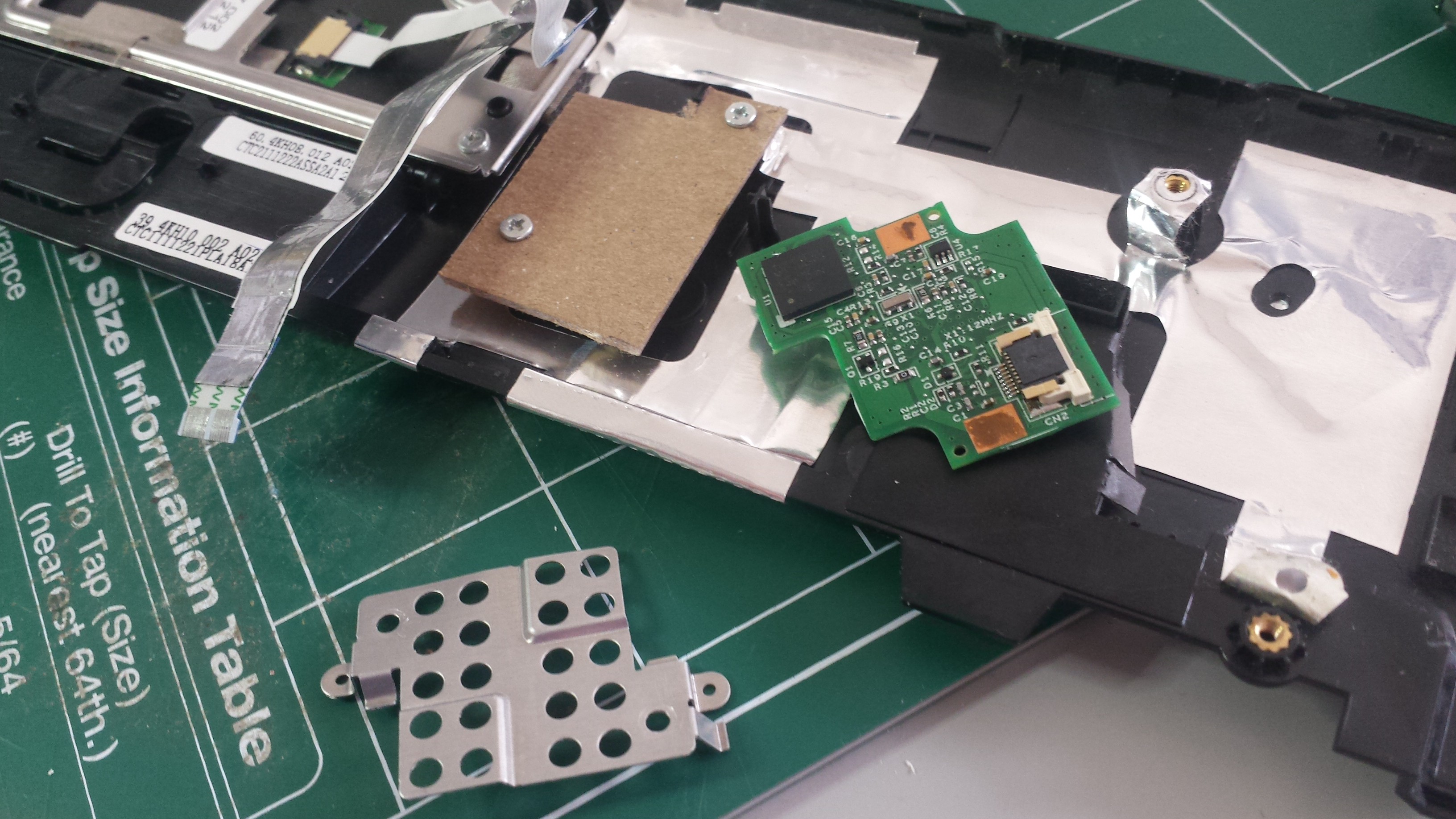
(above: getting rid of the thumbprint reader/metal shield and replacing them with a cardboard template. Yes it kind of looks like a backwards Utah.)
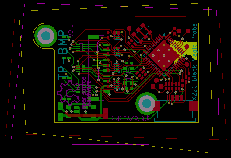
Putting everything in KiCad suggested that the shape and size above would work given the connector location constraint and the component footprints. This design is quite a bit larger than the original Mini and has components on both sides; this made PCB layout quite a bit easier than the Black Sphere design:
After reflowing the QFN STM32 and soldering the rest of the board together (other than the level shifters which are backordered, ugh), a fit check suggested that the hole spacing needs a tiny bit of adjustment but works well enough for v0.1:
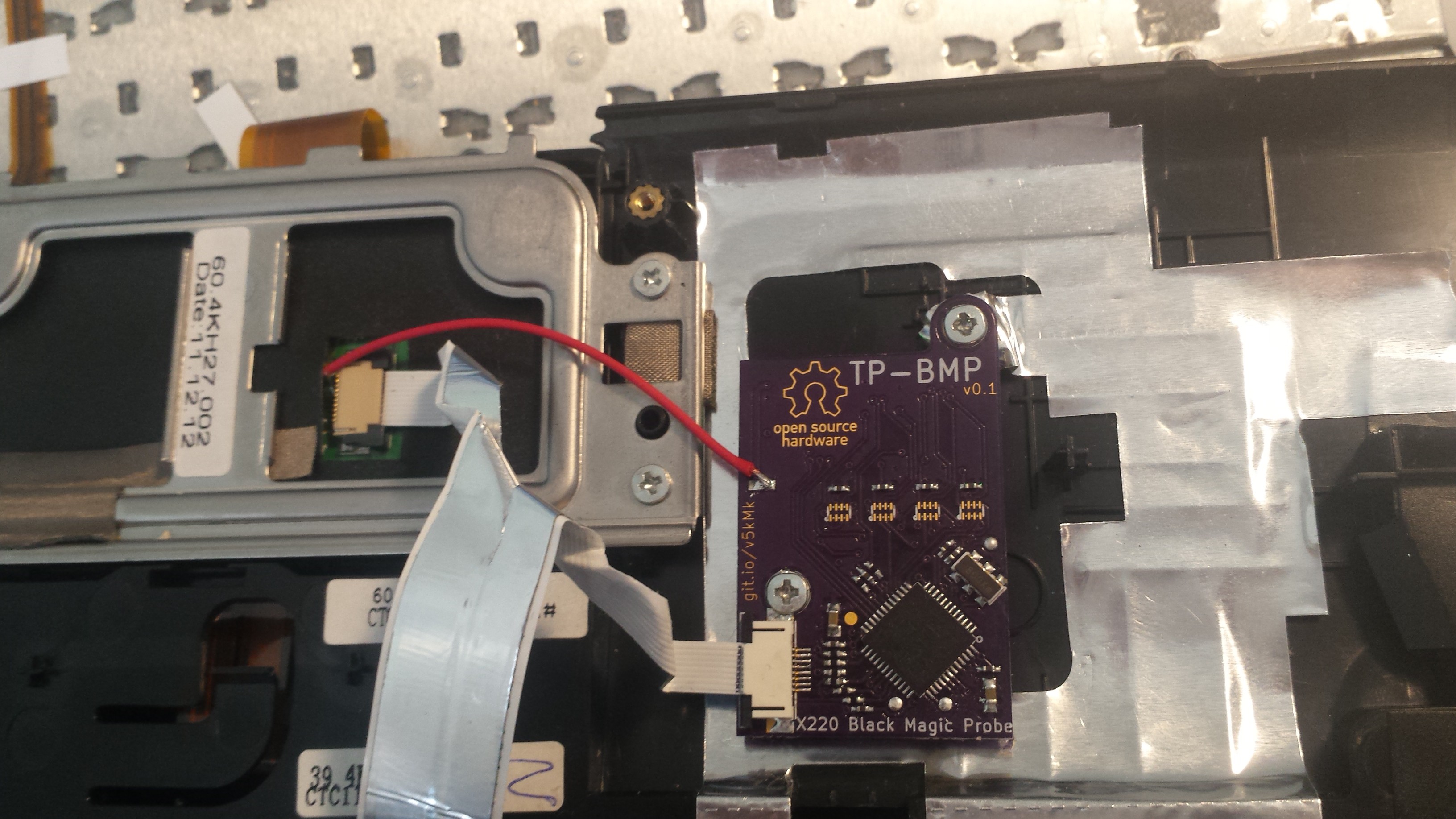 [above: TP-BMP installed in the X220's palm rest. Note missing level shifters. Also the cutout for the fingerprint sensor had to be widened a bit to clear the 10-pin JST header.]
I forgot to take pictures of the firmware loading process; in the image above, one can see the test pads below the STM32 that were used for this process. A Discovery Board was used (well, its ST-LINK, at least) along with st-link to load the stock BMP firmware and bootloader binaries. After re-installation, the board enumerated (!!!), so now it's time to drill LED holes, finish the wiring harness, and solder on the level shifters (when they arrive).
Discussions
Become a Hackaday.io Member
Create an account to leave a comment. Already have an account? Log In.