I tried to fight procrastination and while it's fun to prepare, gather the parts and imagine things, implementing is still important, despite the higher efforts... I think I solved most of the issues so I decided it was about time for action, instead of starting yet another sub-project :-D
One part (the ROM/ASM switch) is still missing and might be delivered late but it is not essential and it can be added later. All the other switches are here so let's go !
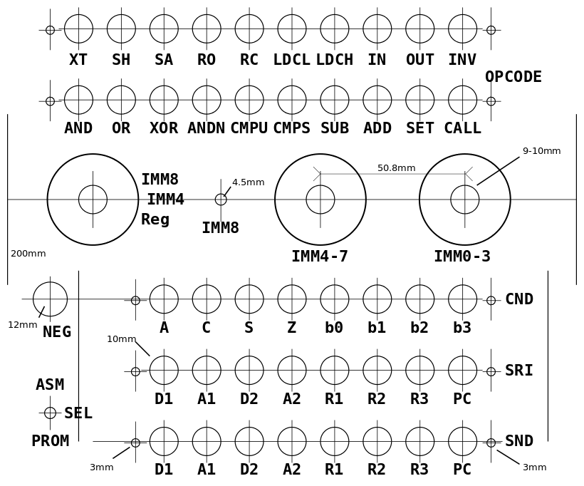
I have uploaded the DIA files for the layout of the buttons and switches. They are laser-printed on normal paper, which is then glued (with a glue spray) on a suitable aluminium plate (found in my archives). So far the expense is about 8€ for the glue spray :-)
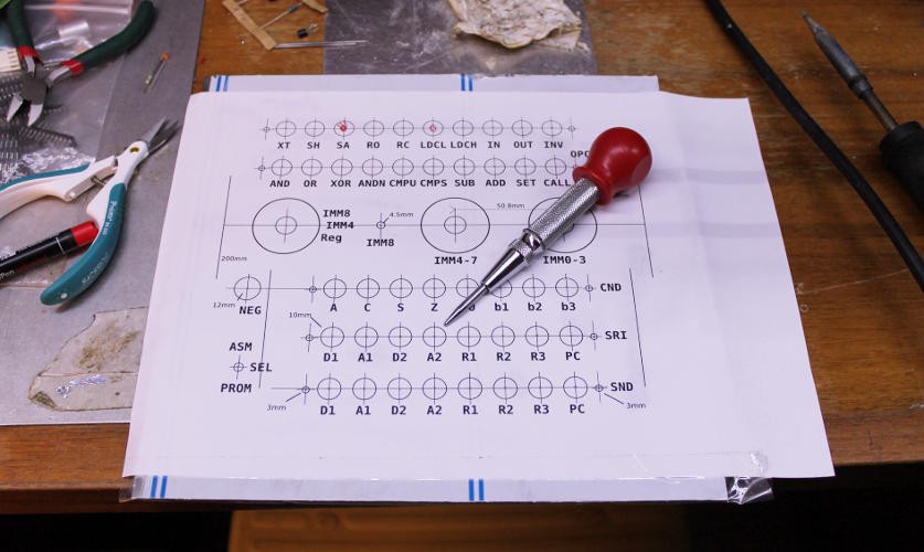
Once glued, the centre of each hole is punched to help later with the drilling.
Drilling took "some time" because of the required precision and odd diameters but my neighbour Alex greatly helped ! Thanks dude ;-)
Overall, the result is surprisingly satisfying and close to my expectations :-)
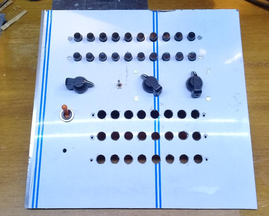 The action of the buttons is great and I did my best to not make it too compact, which also helps for the wiring on the other side :
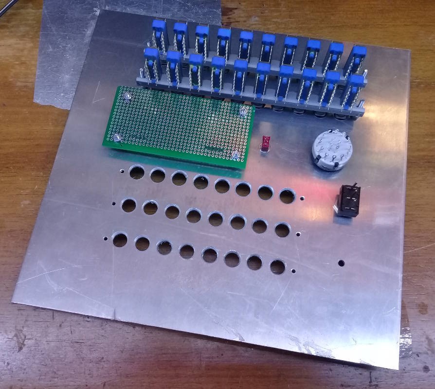
The two hex encoders don't have the appropriate nuts and can't be fastened to the alu plate, so I made a mezzanine PCB, which will later host diodes as well.
The 3 lower rows of buttons have some alignment issues and need filing and adjustments, that's more work but the rest was almost smooth :-)
Better pictures :
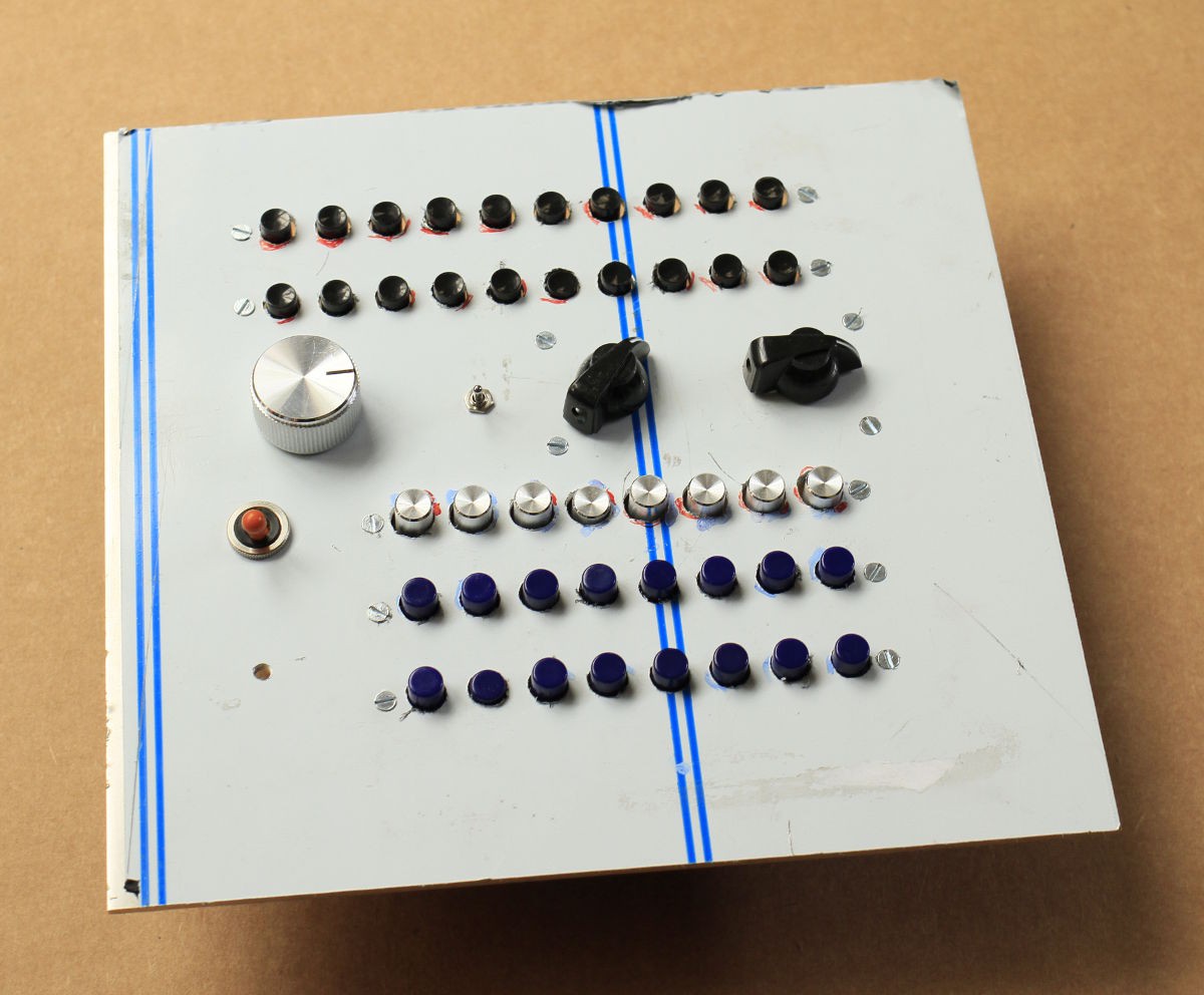
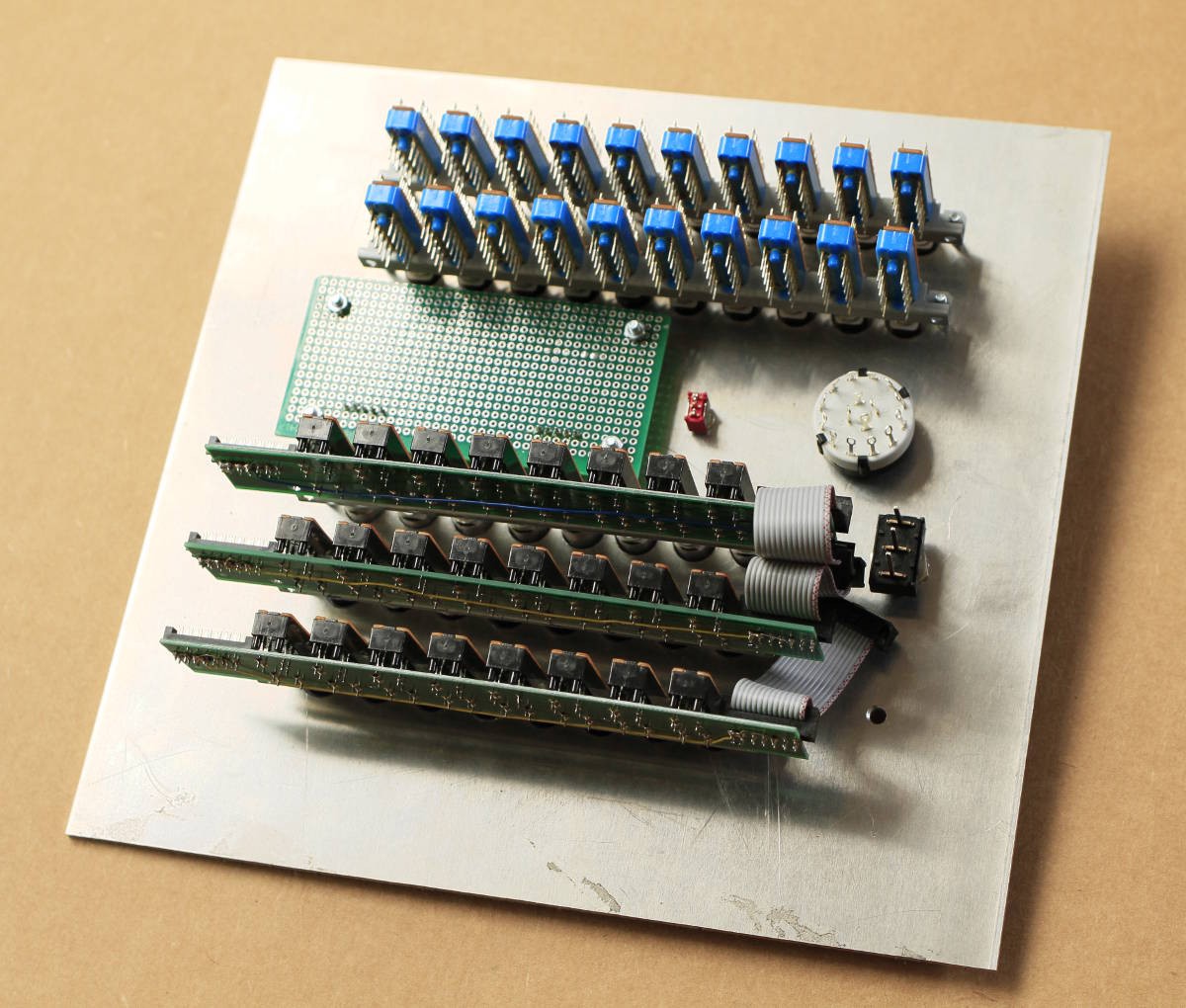
Nothing is wired yet : I need a way to "laser print" the marks on the alu plate.
 Yann Guidon / YGDES
Discussions
Become a Hackaday.io Member
Create an account to leave a comment. Already have an account? Log In.