 Yann Guidon / YGDES
It strikes me only now that I must have under-estimated the importance of magnetic interferences between relays...
I remember seeing placement recommendations for miniature Chinese relays but the РЭC-64 has a tubular shield. How do the openings at both ends behave ?
Having two relays on a well-spaced prototype breadboard can't show the effects of many relays packed densely and switching with weird patterns.
I'm starting to consider using mu-metal sheets but I wonder if it's practically effective and the right solution, because I still have some freedom to organise the parts in space and optimise the magnetic field...
Shoud I start playing with, or even build, a flux-meter ?
Update :
Here is the seller for the RES-64 :
https://www.ebay.com/itm/RELAY-RES-64A-726-REED-SWITCH-9-11V-NOS-USSR-LOT-OF-20PCS/232803573730
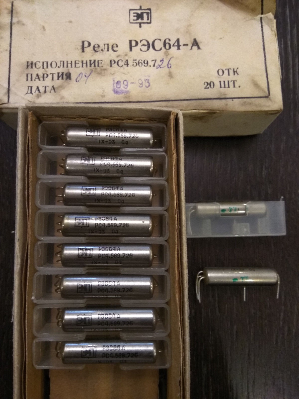
It's a SPST reed relay, you have the two contacts going out of the glass tube available at the opposite ends. The glass tube would be surrounded by the electromagnet coil, the whole is inserted in the metallic tube to further direct the magnetic field and shield a bit from outside influence. I still have to examine a non-working piece to confirm. An additional pin connects the "case" to ground (for example).
In the expected configuration, the relays will be paired and receive the same current, except during a set/reset pulse.
I'll have to check and measure the magnetic field at the ends of the relays. That's one excellent reason to finally use all those UGN3503 I bought for another project !
In the end, working in pairs might solve the problems I imagine so far.
One way to see it is with both relays forming a magnetic loop, to close the static field. I'll just have to find a way to loop the magnetic field, for example by cutting a torus in half. This ensures that the pair of relays is closely coupled, little energy will leak to the closest neighbours.
However, I suspect that the real problem is not the static field but the pulsed/forced changes when a capacitor discharges. This is what can affect sensitive neighbour relays but there is a catch : one relay is pulsed with the opposite polarity of the twin relay... In ALL cases, the magnetic pulse will go against the static field of one relay, while also reinforcing the field of the other relay. There must be an opposition of fields somewhere, a magnetic "hot spot" that can interfere with the nearby relays.
Ideally the programming pulse should have the same polarity for both relays. First it would prevent/limit the cases where one relay has a state different from its twin, in particular during power-on. Second : it would allow the magnetic pulse to be "looped" in a closed magnetic circuit, thus removing many causes of magnetic leakage and interference. The problem is that it would easily double the power drawn by the register set, since there would be 6V to be dropped in resistors... The whole register set would dissipate 2W instead of 1W.
Yes this log needs more drawings...
20200327 :
I just found new information in a totally awesome book dedicated to relays !
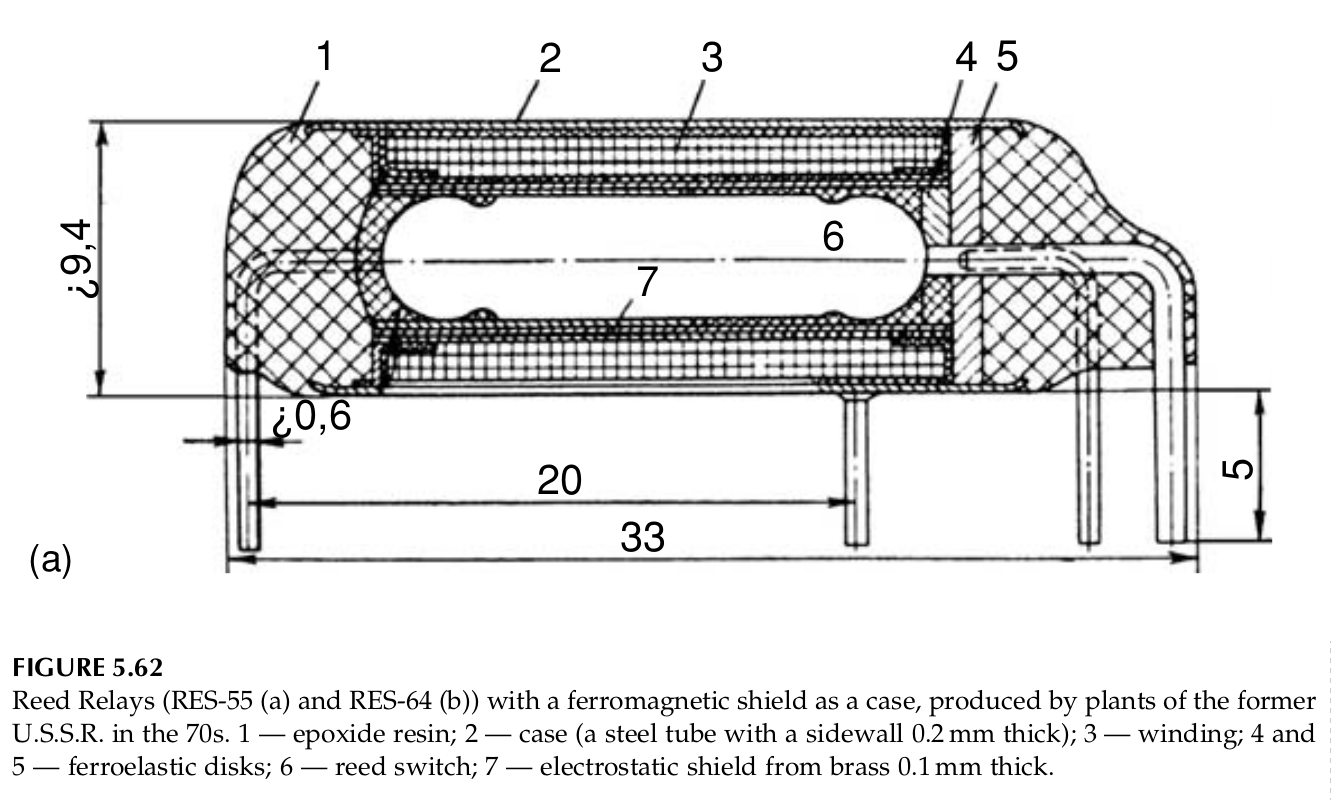
The book is "Electric Relays Principles and Applications" by Vladimir Gurevich and it covers occidental as well as soviet relays. A truly fascinating encyclopedia that turns an apparently dumb device into a marvel of engineering !!!
Notice the element n°5 : what is a ferroelastic disk ? anyway it might prevent the magnetic field from escaping from one end, which is also great to reduce interferences from neighbouring switching relays...
Discussions
Become a Hackaday.io Member
Create an account to leave a comment. Already have an account? Log In.
I suspect it's not much of a concern. The leakage would be at the ends. And the field would diminish according to the inverse square law. Maybe you could try surrounding one relay by 8 others to see if you can affect the central one.
Edit: Sure by all means measure the field that's fun too but there is a case to be made for initial optimism in design in common scenarios because the component makers (usually) have thought of it. I'm thinking of a Kicad neophyte was unsuccessful finding a DPST switch symbol for a tactile switch because it had 4 pins. But they were actually in connected pairs, and there was already a suitable tactile SPST switch symbol with two of pins "1" and "2".
Are you sure? yes | no
As I use these relays in "hysteresis mode" to hold/store a value, external influences might weaken the magnetic storage, which is why i'm so concerned.
Usually you can leave one relay alone under constant power and it will hold its value/position.
Here I'll have 128 relays (8×8 pairs) with wide patterns of activity, that I initially wanted to pack closely to save room, and a neighbour's activity might slowly weaken stored field.
I think I'm slowly coming to a solution, that will mature in the coming days or weeks :-)
thanks for your comments and feel free to interject :-)
Are you sure? yes | no