 Yann Guidon / YGDES
First, here are the logs that describe the design of the Test Access Port :
4. The YGREC debug system contains the first high-level description, the principle applies equally for any technology/implementation.
16. Inspect and control the core
24. Synchronous Serial Debugging
25. MUX trees
109. Gray counter (reboot of the low-level design)
110. The art of large MUXes
111. The first half of the TAP
112. Design of a TAP : the SIPO Controller
113. The TAP's bits counter
114. The TAP selector
115. The TAP is coming together
118. The TAP's eXecute module
119. The TAP crosses 3 clock domains !
.
This log summarises the high-level view from the debugger's perspective. The TAP is "just" a low-level port, a few pins that serialise data in and out of the core, and could be implemented in whatever way (the current TAP is serial but could be made in byte-parallel for the relay version for example).
This TAP is obviously byte-oriented and designed for SPI mode 0 : this eases programming a lot because most CPUs have a byte-oriented SPI controller. Using variable sized framing would operate slower on platforms such as the Raspberry Pi for example. JTAG often handles sequences of bits in groups other than 8...
Timing
The diagram below shows the typical timing with only one transmitted byte shown:
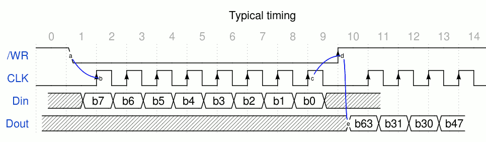
The TAP works as 2 phases in half-duplex, so Din and Dout may share a tristate pin for example. The /WR pin controls the phase and things happen during these transitions.
- Going from high to low starts transfer on Din into the TAP, "full bytes" at a time (the number of bits is always a multiple of 8, MSB first to follow the common SPI standard). Each bit is sampled on the rising edge of the clock. The delay from a to b , as well as c to d, is typically one clock cycle to give enough settling time to the internal counter.
- Going from low to high starts the shifting out of the data from the TAP to the host controller. The 64 bits are serialised with the MSB first, followed by bits from shuffled positions. Bit 63 is presented very soon after the transition (see d->e) so it can be polled without having to shift data or trigger a SPI byte shift. If more than 64 clock pulses are sent, the internal counter wraps around and serialises the same sequence of bits (though their values might have changed since).
The MUX
For practical reasons, the Y8 has a selection of 64 bits to provide a (partial but sufficient) snapshot of the core's state. Instead of reading all the registers, only 4 byte values are available (SND, SRI, Result & PC), which already amounts to 32 bits. The remaining bits are further halved by providing the current instruction (16 bits). The rest is shared by the Status Flags (C, S, Z : 3 bits), the FSM status and a free byte (possibly multiplexed with the scan chain for a loopback test).
In a sense, the order matters little because the bits are scrambled anyway. With the serial TAP, the user must stream 64 bits every time to get everything (this is not the case though for the scan chains and this saves some time). However it's "good" that they fit with the structure of the tree, so it helps with place&route. "Just in case" I placed the fields in increasing order of granularity and relevance to the debugger (in case a byte-wide, or non-scrambled, interface is developed).
TAP/MUX64 allocation of the inputs :
8 bits : Status (Flags & FSM)
8 bits : (undefined, variable, switchable, maybe the selector address ?)
16 bits : Current Instruction being decoded
8 bits : PC
8 bits : RES
8 bits : SRI
8 bits : SND
Notes:
- If a byte-parallel interface is defined, it gets the status immediately, without having to scan past the other bytes that might be unnecessary in a given context)
- This map is defined to be valid after a Null command, where the Selector is reset. Other registers (such as the breakpoints) could be selected by the Selector
- The debugger gets these 64 bits, regardless of the actual implementation : that is the "view" for the GUI which has to manage higher-level multiplexing, sequencing etc.
- The order of the bits matters. Beware with the mapping of MUX64 which can be bit-reversed or byte-reversed. The transient b7 of the first byte is always output first (even before the first clock pulse is sent) regardless of the permutation. This is used to poll the state of the FSM and check when a Trap occurred (for example). Instead of shifting all the 8 bytes, the controller can simply read the Dout bit repeatedly, without sending a clock cycle.
- To ease writing, the internal count order is reversed by the MUX64, so the Most Significant Bit always comes first. VHDL vectors are usually "downto" direction...
- Definition of the first byte :
Byte 1: Status (Flags & FSM) (MSB first)
    b7 : RUN state from System FSM (transient)
    b6 \ System FSM state
    b5 / (RESET, LOAD, STOP, STEP)
    b4 \ Instruction FSM state
    b3 / (IDLE, INST, LDCX, WrPC)
    b2 : Zero flag
    b1 : Sign flag
    b0 : Carry flag
The scan chains
The previous logs have already defined a number of messages :
- NULL : toggle the /WR pin without changing the clock line. This resets the Selector register and should get a clean state, like a RESET (which the TAP doesn't have).
toggle /WR high (just in case)
toggle /WR low
toggle /WR high
- Select : 2-bytes message
toggle /WR low
byte 1: chain selection (valid values : ASCII '1' to '6' so far, avoid '0' and '7')
byte 2: signature=ASCII 'S'
toggle /WR high
This enables one of the sub-chains. To select the chain 2, just inject "2S".
- Execute : This 4-bytes command is very powerful. It is always active, regardless of the selection. This means that the instruction word will be flushed every time new data is shifted in (but in most cases this is OK).
toggle /WR low
byte 1: Instruction MSB
byte 2: Instruction LSB
byte 3: Command
byte 4: signature=ASCII 'X'
toggle /WR high
The command byte must handle 2 things :- What to do with the 16 bits ? The instruction is stored near the decoder's input but should it be used/Muxed ?
- The command/message sent to the FSM. This is how you send the Start/Step/Stop/Reset commands (and others).
* bits 7, 6, 5 : reserved / not decoded
* bit 4..1 : FSM command
4321 : bit
0000 : NOP
0001 : STEP
0010 : START
0011 : STOP
0100 : RESET
0101 : Write TAP word to instruction memory at address PC.
0110 : Write TAP word to compare mask buffer
* bit 0 : Instruction MUX
    0 : Decoder reads instruction from the Instruction Memory
    1 : Decoder reads instruction from the TAP Instruction buffer
         (only valid for NOP and STEP)
So the NOP and STEP instructions have 2 versions : NOP/NOPX and STEP/STEPX depending on the LSB value, each with their own purpose. How convenient: only bits 4,3,2 require decoding with a NOR3.
START uses bit 7 as an extension :0: Normal execution 1: Enable the instruction compare trap
The expanded commands are :NOP : 00000000 : Not an operation. Just don't mind. NOPX : 00000001 : inject an instruction in the core. State must be STOP. STEP : 00000010 : execute one instruction and advance PC. State must be STOP, goes back to STOP. STEPX : 00000011 : execute provided instruction, don't advance PC. State must be STOP, goes back to STOP. START : 00000100 : resume/start execution of instruction stream. State must be STOP. STARTC : 10000100 : resume/start execution of instruction stream. State must be STOP. Enable trap on instruction comparison. STOP : 00000110 : interrupt RUN state. RESET : 00001000 : Just stop everything. Send a START to reload instructions and run again. WRIMEM : 00001010 : Write instruction buffer into instruction memory at address PC. State must be STOP WRMASK : 00001100 : Write instruction buffer into the comparison mask register. State must be STOP
More commands will be defined later, using the MSB as extensions or extra fields (such as the Write Trap commands).
Check the update in 118. The TAP's eXecute module
More messages will appear later, for example for the trap mechanism.
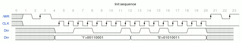
Init sequence
The TAP can be initialised by writing to registers that have no /RESET input (most).
- NULL command
- "1S" command -> strobe the TAP internal RESET signal tied to register bit 1.
- NULL command (again : end of strobe)
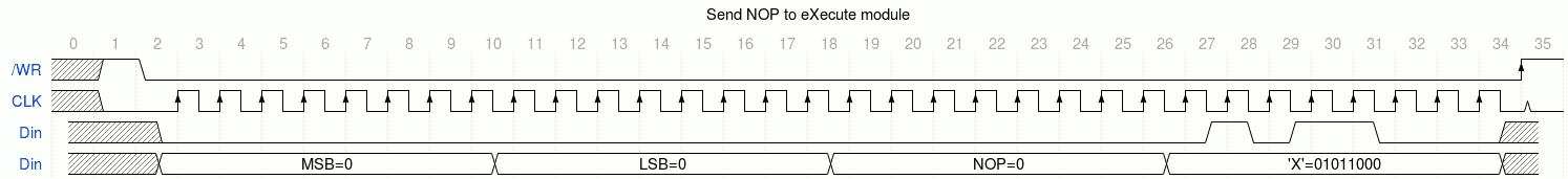
- Send NOP to Execute : 000'X' (clear the instruction register and ongoing commands)
Here is how it looks with Wavedrom:
And the last part :
.
.
.
.
Discussions
Become a Hackaday.io Member
Create an account to leave a comment. Already have an account? Log In.
TODO : exec commands with PC+1 option
Are you sure? yes | no