 Yann Guidon / YGDES
20200814 : back to 6 bits because it looks unlikely I'll use 16 byte-long messages. Look at this circuit :-)
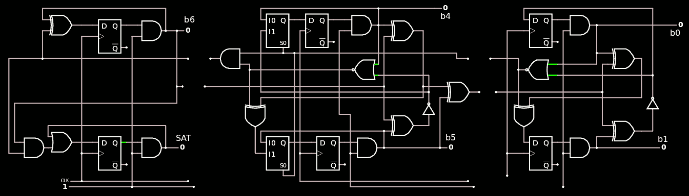
 Total count : 39 gates :-)
The rest of this log is still very informative.
With the new TAP v.2, I reconsider the detailed design of the whole circuit and merge the two counters into one. This means that I must remove the /RESET input of the DFFs, which in fact are not desired because basic ASIC gates don't have one anyway. I must also increase the size of the counter a bit and add a SAT output (plus some pre-decoded bits such as FB or NULL). With these enhancements, the same counter can drive both the MUX tree for Dout and the other decoders for Din.
The log 109. Gray counter explains all the details of the construction of a modular/cascaded Gray counter, check it out if you haven't seen already !
From there the first step is to expand the counter to 7 bits and add a saturation bit :
Then the DFF with RESET must be substituted with a DFF and a AND2 gate.
Let's start with the MSB : SAT and B6
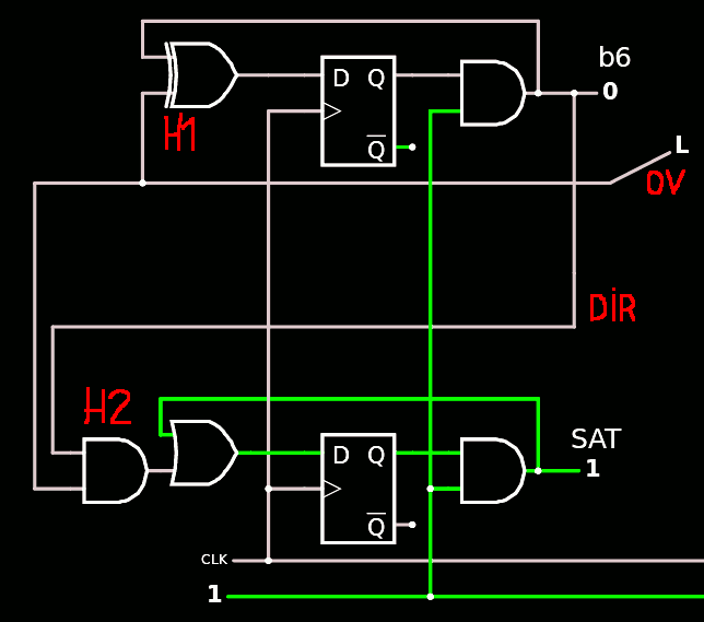
The funny thing is that the AND and XOR gates can be understood as a half adder, because B6 is toggled every time OV is on, and SAT is enabled when both OV and DIR are on. This could help simplify a bit if a "half adder" gate is available in the ASIC PDK but H2 seems best merged with the following OR2.
The DFFs have no RESET input as expected. The SAT output could even drop the DFF but it would be ON during cycle 127 and not 128, thus reducing the usefulness of the whole circuit. The DFF delays the flag by one cycle and allows the use of the full 16 counts.
The middle module(s) have nothing specific to be said about...
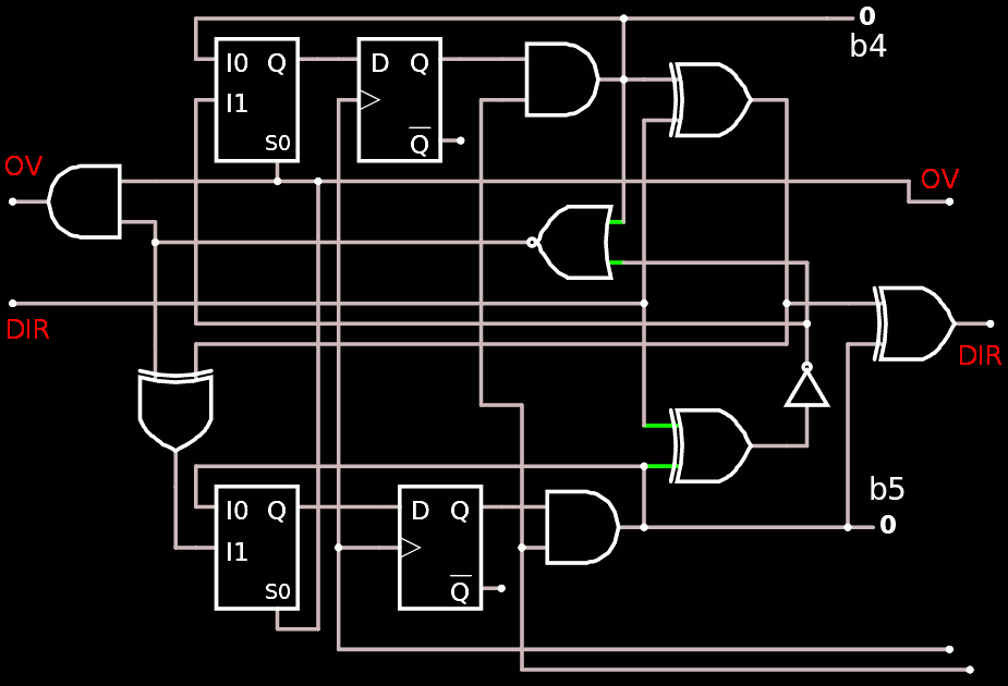
I simply added the AND2 at the output of the DFF and removed the RESET pin.
Same for the the LSB : it's a simple adaptation.

.The modules are gathered in this link so they can be reused and adapted later for other eventual purposes.
I hope it will be useful to others ;-)
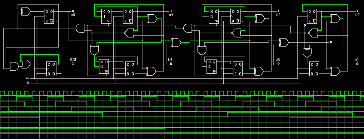
The whole counter is there : it looks like such a mess that I'm glad it's modular ;-)

And it works nicely when driven by the circuit described in 120. TAP v.2 :
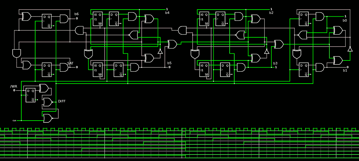
(of course this is not the typical way to use it but it works anyway)
Now, writing it in VHDL is another story.
Stay tuned !
Oh I almost forgot ! The earlier Counter unit has a FB output that is needed in most of the other circuits. It turns out it's quite easy to generate but not as I originally thought : just AND the DIR and OV signals from the LSB module. The circuitjs diagram shows that the result of the AND is a bit glitchy on the the 4th (mod 8) cycle but the DFF resynchs the signal. The AND result is provided as a partially decoded signal preFB, in case it's needed in other places...
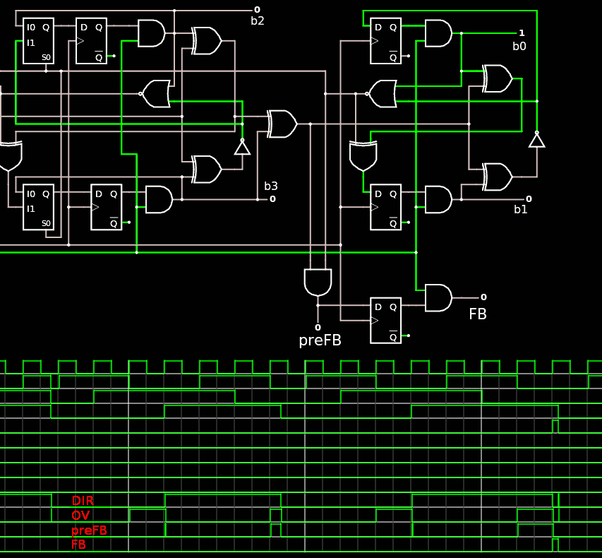
The trick is to ensure that the /WR toggles work as intended, there is a AND after the DFF, and there is no need to AND before because the OV and DIR signals are already ANDed anyway.
It is also useful to provide pre-decoded flags for when the byte count is low. I added the Less4 output signal that is a NOR3 of SAT, b6 and b5, such that it is 1 when the count is less than 4 bytes.
As the circuit has grown beyond the linking capacity of the site, I saved the description as Gray7s-fb-l4.cjs in the archive.
The whole thing is pretty large, now...
VHDL implementation was not difficult, thanks to the previous version and all the planning that is logged on these pages. It compiled (almost) right away and thanks to rigorous checks during the writing, only one small numbering mistake remained and was easily spotted.
Total count : 46 gates (incl. resynch, sat, FB), while the earlier Counter was 31 and Gray6 was 21 (and with special DFF with Reset). So the net gain is 6 gates but there are 16 DFF that have been replaced with a smaller version without RESET.
This new version will greatly ease the design of the other modules !
Discussions
Become a Hackaday.io Member
Create an account to leave a comment. Already have an account? Log In.