 Yann Guidon / YGDES
I figured a few things...
Here is the aggregated schematic for the opcode field :
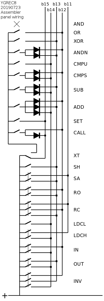
It might look complex but most of the complexity has been examined in the previous log and it's basically a pair of binary encoders that have been chained through the XT button.
The tricky part is the simultaneous selection of buttons from both rows : some combinations would disrupt the binary code. This occurs when the "lower row" (AND through CALL) has one button pushed with a code that has more than one set bit (ADD, SUB, CMPS, ANDN). There is a potential path that is now broken by 10 diodes. And since the locked switches work together, only one switch is now required.
The "upper row" OTOH doesn't need diodes because the switches are interlocked. There is no place where different signals are brought together, except when a switch is pushed.
I'm working on the other switches...
More schematicsing :-D
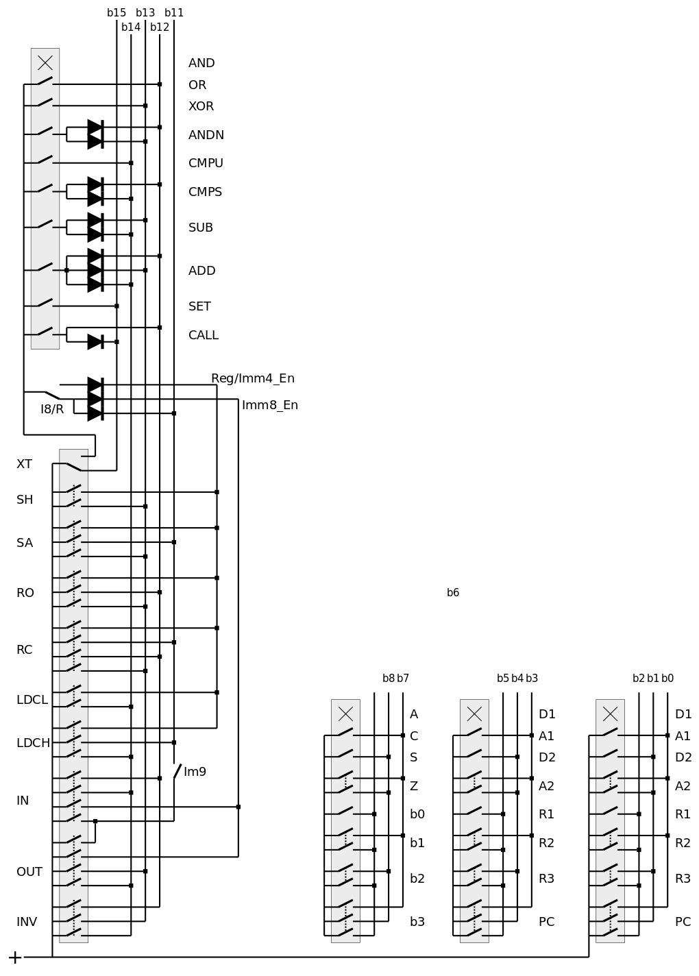
Going further, I added the dual hex encoders and tried to join everything together:
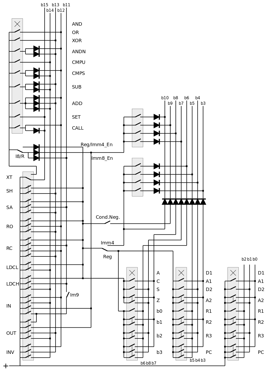
It's almost complete. b2,b1,b0 didn't change, nor did b15,b14,b13,b12,b11. The SRI field (and the LSB of the condition) can be combined with the lower half of the immediate field, while the condition field (plus a couple more bits) can be combined with the higher half.
However the simultaneous activation of the lower half for both Imm4 and Imm8 is more complicated and not yet implemented. The trivial version would use another diode, so the total drop would be 3 diodes !
I need a method to reduce this drop, I suspect there is a way to keep it down to 1 drop but I need to test it...
And I should switch from dia to EAGLE :-D
I solved a potential problem caused by several diode drops in series :
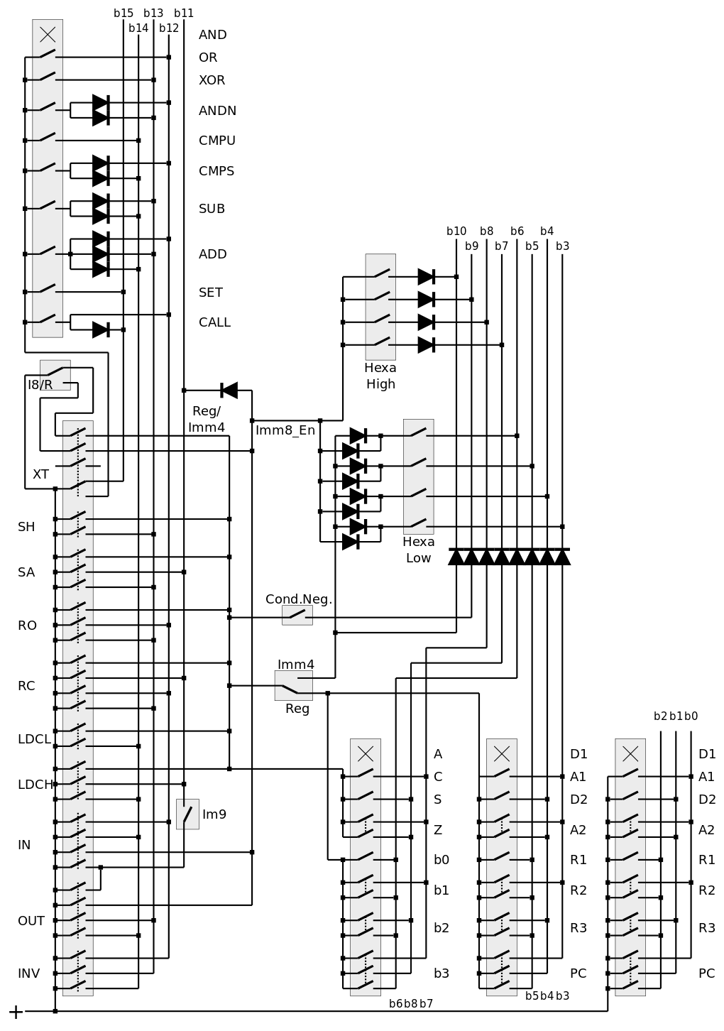
The free switches for the XT button isolate the main signals and prevent the use of diodes. The hexadecimal encoder requires separate switches, so each signal can be driven by a pair of diodes (instead of one diode at the output).
There is one remaining switch and I wonder how to use it to remove more diodes...
Discussions
Become a Hackaday.io Member
Create an account to leave a comment. Already have an account? Log In.