 Yann Guidon / YGDES
As you can see at Log: Don't go full Numitron ! Unless... OK whatever., I started to design the disassembler and I totally renewed the look:
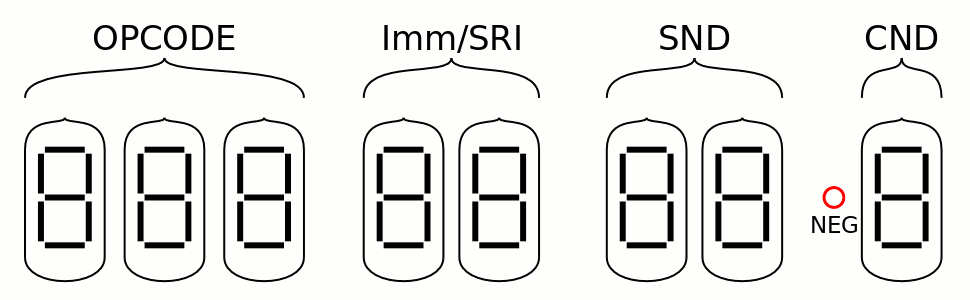
This version now shares a pair of Numitrons to display either the SRI or the Immediate field, which saves a bit of room and 2 tubes but adds some complexity in the decoding logic (yet not enough to scare me, of course). The above display is not compliant with the normal assembler but close enough and it gets the job done :-)
I draw a lot experience from the #Numitron Hexadecimal display module so I know what to expect and what to do to display the desired patterns on the 7 segments. There is no technical challenge anymore to display the CND, SND, SRI and Opcode fields, but it's still a lot of work, in particular for the Opcodes: this decoder not only must display 19 words on 3 tubes, but also sends control signals to enable the other fields.
It's going to be small and gorgeous but behind the front panel, the electronics will be pretty dense and draw a significant amount of power...
Damnit I forgot that IN/OUT have 9 bits of immediate address...
The Imm field will create more problems, on top of the multiplexing with the SRI decoder. The field must select the width between 4, 8 and 9 bits. The last case is not a problem because an address is just a positive number. Imm4 is sign-extended to 8 bits (easy: 4 relays) but should Imm8 be represented as a signed number ?
Then there is the special case of Add imm4(>=0) where Imm4 is incremented.
The easy way is to simply display the number as is, and forget about it, though the display would not be accurate. It would even be misleading.
But then, if the Add correction or the negative display are implemented, an increment unit is required. And negative numbers require a XOR to transpose to positive numbers. This means more circuits in front of the display modules...
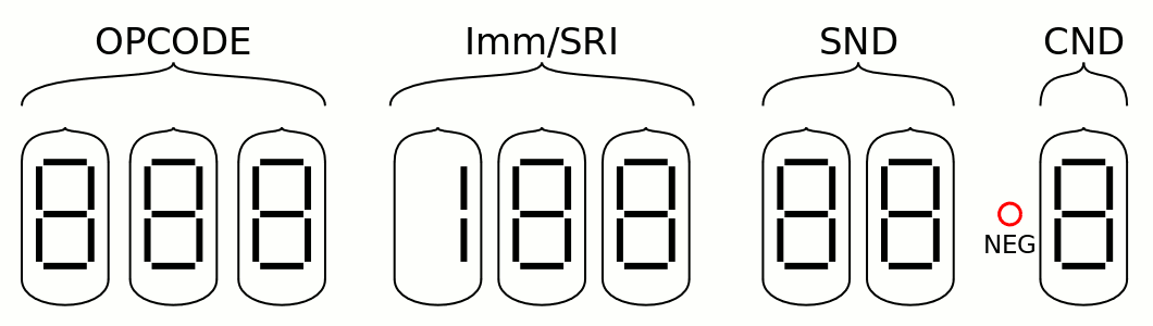
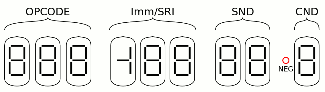
But with negative numbers, the added Numitron can have another segment used, for the sign bit:
To keep the system modular (and help with development, debug and repairs), I think I'll make 3 modules with 3 Numitrons each, with identical connectors. I can then develop all 3 groups in parallel.
The connector is probably IDC 2×13 : each Numitron has 7 segments + 1 common signal, or 8 wires, and 3 Numitrons need 3×8=24 wires. Add two positions for a pair of pins for the optional red Glühbirnchen and we have exactly 26 pins.
Discussions
Become a Hackaday.io Member
Create an account to leave a comment. Already have an account? Log In.