 Yann Guidon / YGDES
In the log Don't go full Numitron ! Unless... OK whatever. I examine how to reuse the techniques developed in #Numitron Hexadecimal display module and apply them to decode all the fields of the Y8 instruction.
For the register name I came up with this diagram :
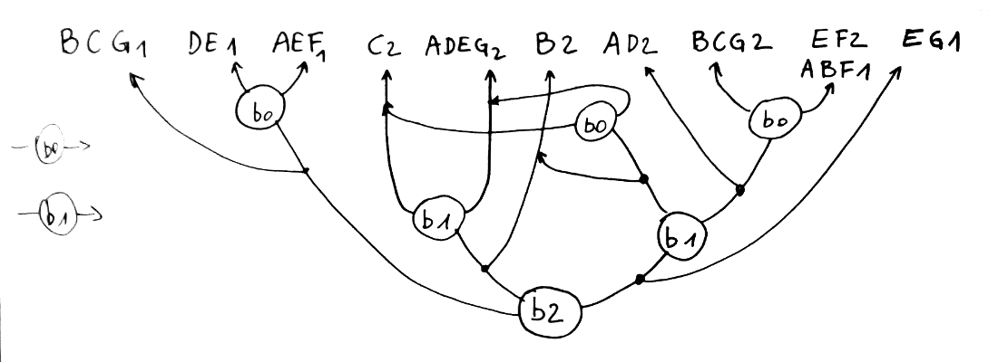
This decodes to the following symbols :
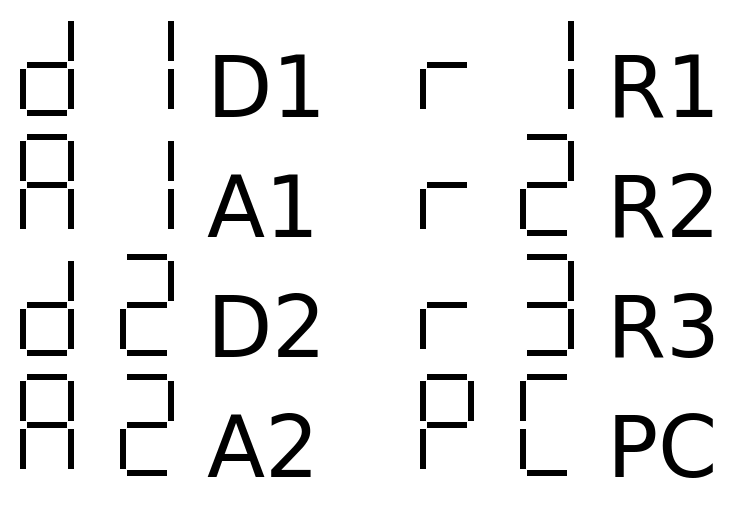
The segments E1 and G1 are always on (for A, d, r and P) so I modified the diagram a bit, later.
I didn't optimise the replicated 1 and 2 because it would make the relay side too complex for little gain (I only have to build 2 decoders). Here is the result :
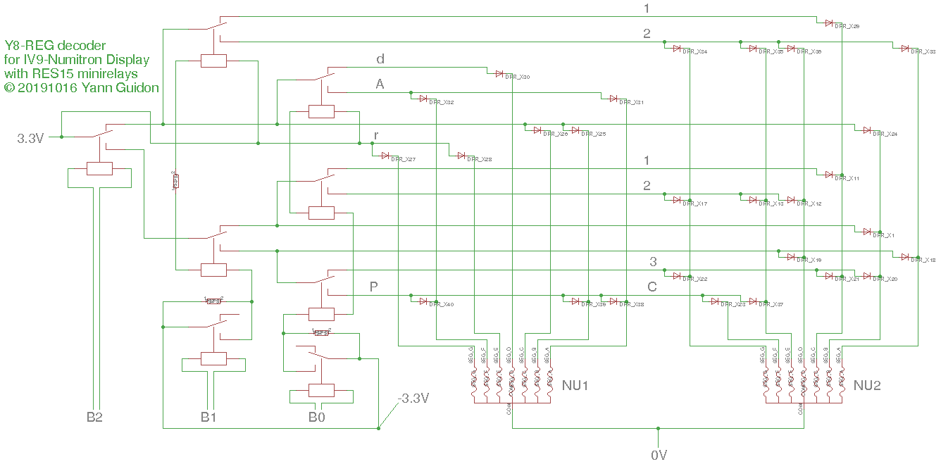
To test the circuit, I have built a test device with a "standardised" 26-pins connector and 3 Numitrons. To inject data, I will reuse the connector and pinout of the existing Numitron hexadecimal modules.
Note : the module can be powered down by disconnecting the +3.3V power line. The diodes will prevent shadow segments anyway, even if another decoder is connected in parallel to the Numitron (for example to share the Imm4 and Reg formats).
Discussions
Become a Hackaday.io Member
Create an account to leave a comment. Already have an account? Log In.