 Aric Caley
Power
I 'upcycled' a portable battery bank that you can buy almost anywhere for just a few dollars. These little banks almost always have the same kind of standard Li-Ion 3.7 volt batteries inside. They are reliable and easy to work with (Li-Poly battery packs can be easily damaged). We really need a minimum of about 5v to power the Arduino and the LED's for decent brightness, so these little battery backs contain DC-DC converters to make that 3.7v into 5v, in addition to the charging circuit.
Because I didn't want to try and pack in full USB cable and connector, I simply soldered two wires onto the back of the USB port. There are four wires and you want to connect to the outermost two wires. If you are looking into the end of the USB connector, the right side is the ground and left side is the positive.
Alternatively, you can just buy the battery and a charger as listed in the parts list, which is functionally the same and easier to hook up.
Light
Originally I planned on using 2 NeoPixel sticks with 8 LED's each, however my local store didn't have any in stock. Because of this I had to find a backup solution, which resulted in changing everything...
Adafruit Circuit Playground
I stumbled across this really cool little board that has almost everything needed to implement the PID built in. Its an Arduino board with the same type of processor as most Arduinos but packs in sound, light, and temperature sensors, as well as a motion sensor; but most importantly, it has 10 NeoPixels on it. Now, these are mini pixels so they are not as bright, and they are arranged in a circle; but they are still plenty bright enough! And you can get one of these for just $20. Paired with the bluetooth board and its almost too easy.
A Box
You can use any clear box you can find, but I used an Amac box with the dimensions 2 5/16" x 3 1/16" which was just the right size for the height of the battery and the diameter of the Circuit Playground.
Complete parts list
I've included links to where you can get these parts, even though some of the parts I used were from my own supply, and I repurposed a USB battery pack.
- Adafruit Circuit Playground
- Adafruit Bluefruit LE UART Friend
- Tiny Breadboard
- LiIon battery
- LiIon charger
- Clear plastic case
- Power Switch
- Right angle header (3 pins worth)
- Connection wires
- Double sided foam tape
You will also need a soldering iron for the headers on the UART board, some drill bits and an X-Acto for cutting into the box.

 Dimitar
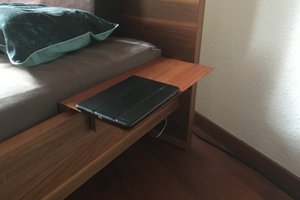
 MSchmidl
 scubabear
 NuclearPhoenix
14 year old me's head in the 80's would have fairly exploded upon discovering NeoPixels. Adult me can't help feel like a kid again, fiddling with these and Arduinos etc..