0%
0%
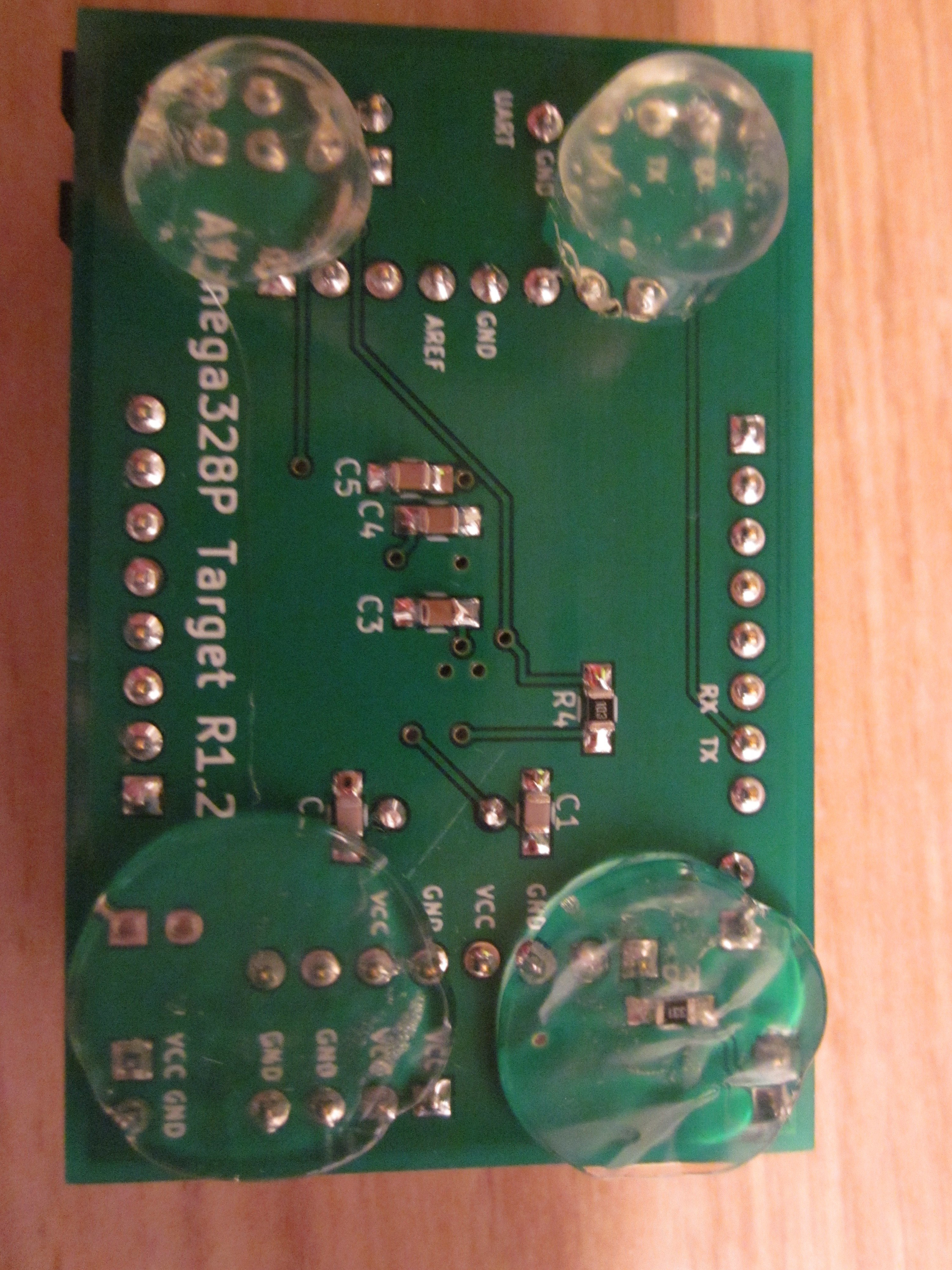
Creative repairs and hacks
A place to post my creative repairs and hacks
Become a Hackaday.io member
Already have an account? Log in.
Just one more thing
To make the experience fit your profile, pick a username and tell us what interests you.
Pick an awesome username
hackaday.io/
Your profile's URL: hackaday.io/username. Max 25 alphanumeric characters.
Pick a few interests
Projects that share your interests
People that share your interests


 Kevin Arne
 Christoph
 zakqwy
Came for the dev boards, stayed for the tips. I love these random tips/tricks projects.
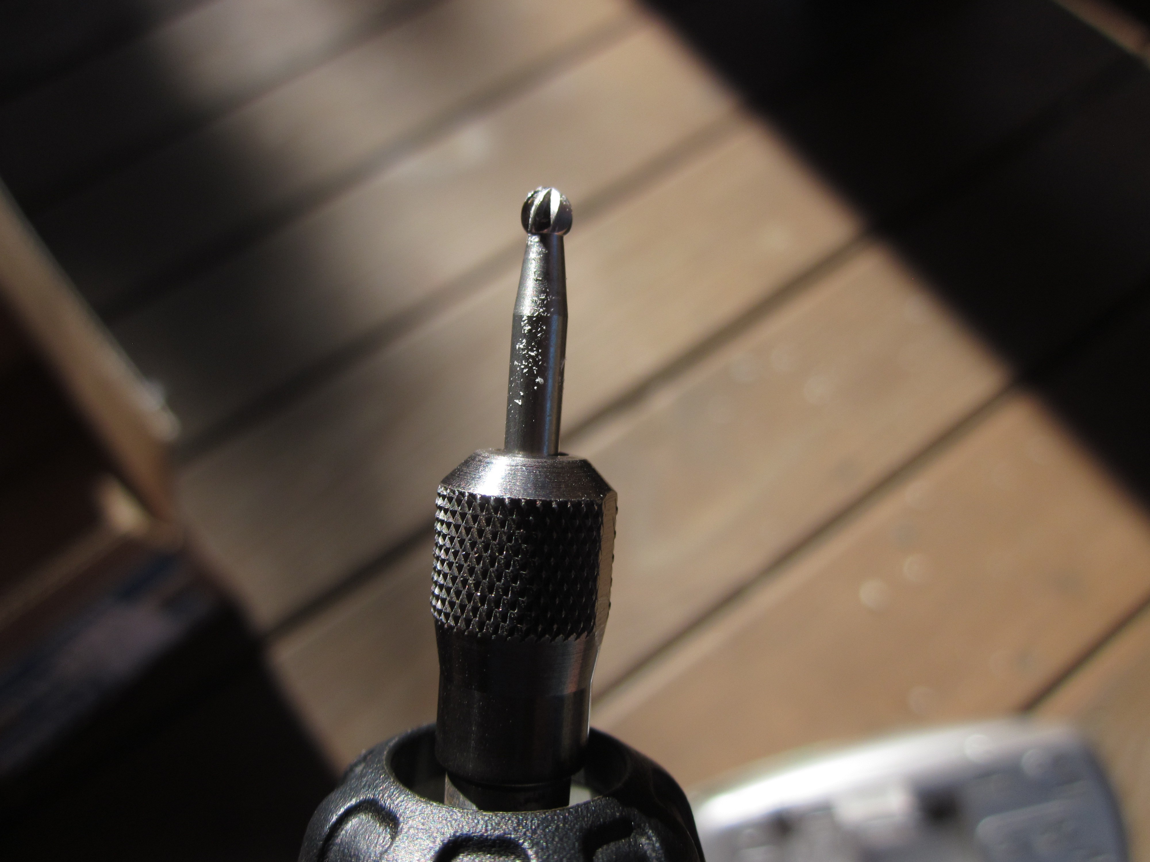
I do the same with hotglue feet, but use non-stick baking paper. I think it's got some kind of high-temp plastic sprayed in a super-thin layer. Anyway, hot glue doesn't even adhere to it, much less stick.