Power supply
Supply is from two AA cells, nominal supply voltage is 2 to 5V ( startup). Once running it will continue to operate down to about 1.2v, depending on load ( in particular OLED content).
Incoming power feeds a MCP1640B boost regulator U5, which boosts the supply to 3.3v.
If the incoming supply exceeds 3.3v, the regulator bypasses, connecting the output to the input, so this must be bourne in mind if the 3.3v supply is used to feed 3.3v-only devices, as the 3.3v rail will be close to the input voltage for inputs >3,3v This is not an issue with alkaline AA cells, but may cause unwanted smoke if supplied from other power sources.
The 3.3v supply is then regulated down to 2.8v by U5 which supplies all onboard devices except the OLED boost supply and white LED.
The OLED boost regulator U3 provides nominally 12.7v for the OLED. The input to the boost inductor comes direct from the battery, but the boost regulator is supplied from the 2.8v supply. This to allow operation when the battery voltage falls below U3's minimum supply voltage.
Power on/off control is via the MCP1640's ENABLE input. The power button forces the device on via D2A. When the MCU starts, it then holds the pin high using IO pin RA4 via D2B, and can power down by setting this pin low. The state of the power button can be read via RA7.
Battery voltage sensing
Q1 switches on a voltage divider to allow the battery voltage to be measured. As Q1's source may be higher or lower than the PIC's 2.8V supply, C12 is used as a level shifter. The POWERCON signal is set low for a very short period while the ADC samples. This period is short enough that the 3.3v supply is not affected by the momentary turn-off of U5. Battery voltage is measured relative to the PIC's internal voltage rererence, so correct results are obtained if the 2.8V rail starts to drop out.
Camera
The camera module uses the OV9650 sensor from Omnivision. There are a number of slightly different modules available on Ebay and Aliexpress. The ones pictured below have been tested & found to work with the badge hardware. There may be slight differences in lens field of view between module types.
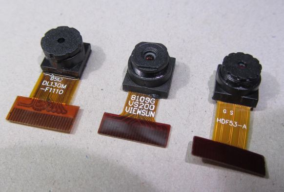
This sensor is one for which quite a lot of documentation has escaped ( see files section ), though this should still be treated with caution as descriptions of the registers are incomplete, sometimes misleading or just wrong.
The PIC reads data from the camera via the parallel master port (PMP) peripheral, via DMA transfers triggered by counters clocked by the pixel clock. The basic method used is described in This video
The method described in the video only captures single pixels every <n> pixels, where n>1 , as the counters cannot generate a DMA request on every clock. This works for monochrome format as you only need the Y component of the YUYV output sequence.
This technique has been further developed In order to capture adjacent pairs of pixels necessary for the RGB565 colour format.
This works by doing 2-byte DMA transfers, and relies on the pixel clock period being the same as the time between the two consecutive DMA transfers. There is a small amount of jitter on the time of the second transfer, but by selecting the PIXCLK phasing, this is kept within the data-valid time of the camera data. For slower capture rates it may be possible to tweak the 2-byte transfer timing using the PMP peripheral's wait-state configuration.
The camera's POWERDOWN line is controlled by one of the OLED's GPIO pins. This is of limited use in practice, as when the camera module powers down, it jams the I2C bus for a second or so as the core voltage discharges ( causing the regular accelerometer reads to hang) , so this should not be used for routine on/off control, but only if a soft powerdown mode is needed. The camera's sleep I2C commands allow the camera to be put in a reasonably low-power mode.
One issue that has been observed is that when underclocking the camera below 12MHz ( which is necessary for some of the zoomed modes), Accessing the I2C bus at >100Khz can put the camera in a state where it jams I2SC SDA permanently low. Briefly pulsing POWERDOWN high seems to clear this condition.
OLED Display
The display is a 128x128 pixel colour OLED, using a SSD1351 controller via a unidirectional SPI interface.
OLED was chosen over TFT as it only consumes power propotional to the pixels illuminated, whearas a TFT draws significant power for the backlight all the time.
One of the controller's GPIO pins is used to turn the 12V supply boost converter on and off. This can be used if a soft powerdown function is needed.
This display is available as a Densitron part ( DD-128128FC-6A) from Farnell, 4D Systems (4DOLED-282815) from Digikey, on this module from Adafruit and This one from Sparkfun
However the same module is available at much lower cost from Aliexpress and Taobao: search for 1.5" OLED and look for this image:

MicroSD card
The MicroSD card is driven via the SPI interface. The CS line is also used for card-present sensing, and the SPI lines are shared with the serial SRAM.
Accelerometer
U2 is a LIS2HH12 accelerometer for motion/tilt sensing.
Serial SRAM
U6 is a Microchip 23LC1024 serial SRAM. this provides additional RAM to allow images up to 320x240x16bpp to be captured ( in conjunction with the MCU's internal SRAM).
Buttons
Most of the buttons share I/O with other pins used by the OLED, SD card etc. These pins are briefly set to inputs to read the button states.
LED
A white LED is available to provide some subject illumination. Note this is powered from the 3.3V supply, so will be brighter if the supply is > 3.3v, and may light continuously at supplies close to 5v as it is driven directly from a PIC pin.
Discussions
Become a Hackaday.io Member
Create an account to leave a comment. Already have an account? Log In.
Thanks! Another question, this time about the accelerometer. Project file "hadbadgeschem.pdf" labelled U2 as "LIS2DH12" and the BOM file "cambadge2.xyrs.csv" lists U2 as "LIS2HH12TR". Is it correct to assume BOM is the final word? Also - any words of wisdom you'd like to share about the accelerometer? If so, please add to this hardware description page. Much appreciated - thanks!
Are you sure? yes | no
Factory test just picked that one up! Protos used DH but production uses HH. I'd not noticed that they had different I2C addresses & register layouts..
If writing applications you don't need to worry about it as the software framework reads the accelerometer for you every 20mS into global variables
Are you sure? yes | no
OLED Display section on this page says it is "using a SED1351 controller".
But the links to the display sold by Digikey and Adafruit both list the controller as SSD1351.
Should we be looking at the data sheet for SSD1351 or SED1351?
Are you sure? yes | no
SSD - SED is an LCD controller.
Are you sure? yes | no