I got curious about this display after browsing the web. Many people are having trouble between two versions (the previous one was a i2c display) and the "Update List" display which implements a canbus interface. This is a simple 8 characters display with great contrast. 2 integrated features: a clock and the external temperature.
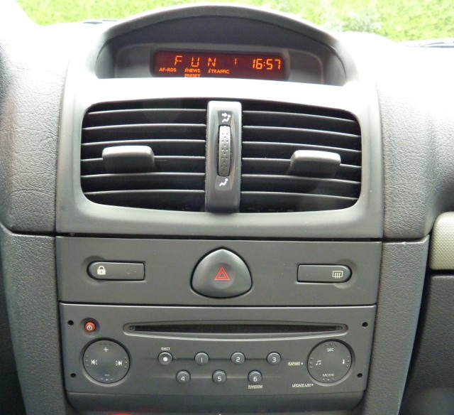
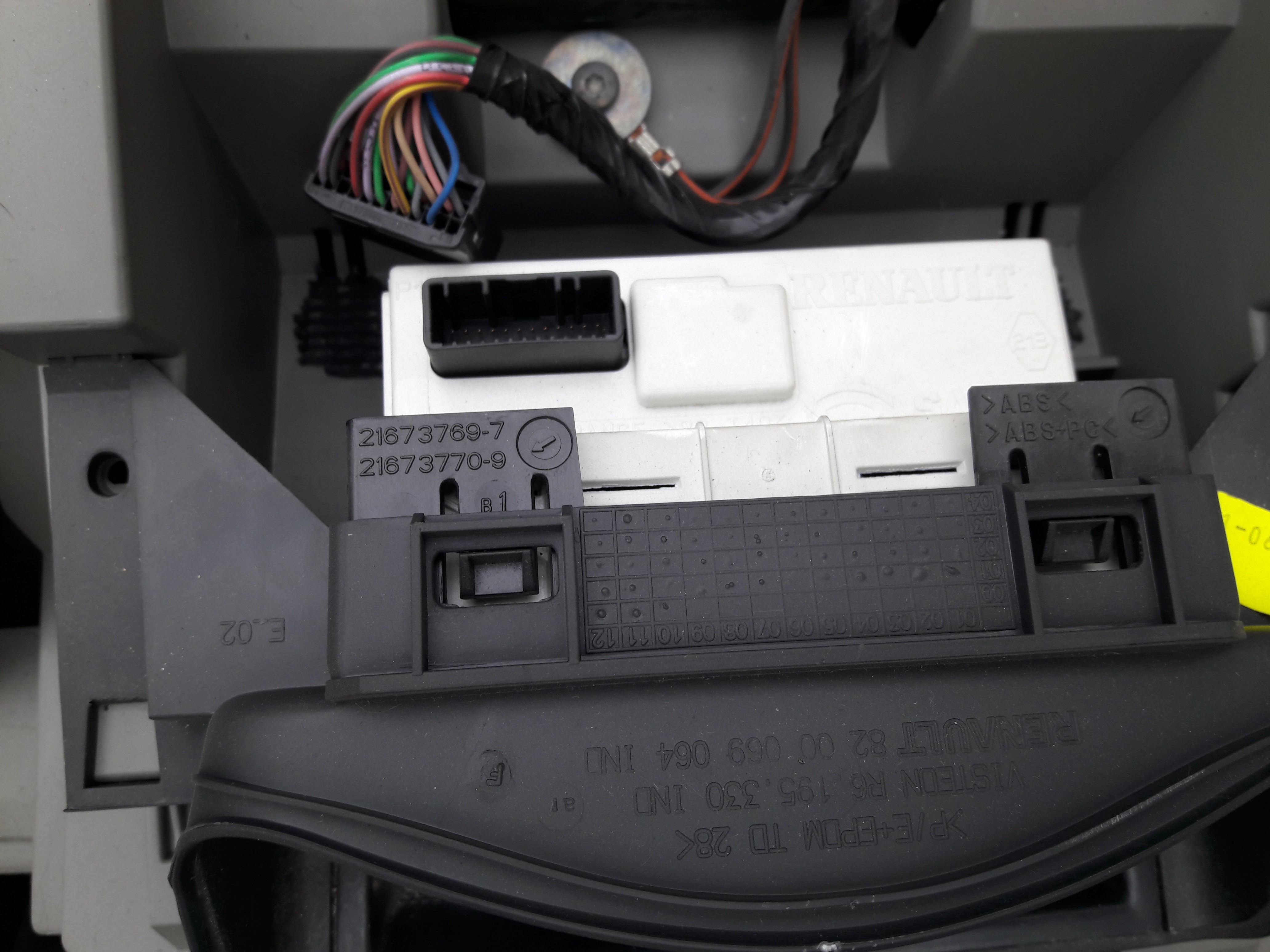 This is an AFFA2 model, ref 8200380298
On different forums, I got the pinout of the display:
1 - Autoradio {green} [3]
2 - Autoradio {brown} [1]
3 - NC
4 - NC
5 - NC
6 - NC
7 - Steering wheel remote control {violet}
8 - Steering wheel remote control {green}
9 - Steering wheel remote control {brown}
10- Steering wheel remote control {yellow}
11- Steering wheel remote control {pink}
12- Steering wheel remote control {grey}
13- NC
14- NC
15- ? Power ( + protected left light ) {blue}
16- Autoradio {grey} [5]
17- 12V (After contact) {yellow}
18- Signal 0V External temparature probe {brown}
19- Probe {green}
20- Rheostat {violet}
21- 12V Permanent {red}
22- NC
23- GND (0V) {black}
24- ?
The useful ones are pins 1 (canbus CANH), 2 (canbus CANL), 17 (+12V after contact), 21 (+12V permanent from battery) and 23 (GND).
As a side note, the pins 7 to 12 are used to decode the steering wheel remote control matrix 3x3 keypad. I'm not gonna use that for my bluetooth HID smartphone remote control. One reason for that: I want to be able to detect multiple key presses, which is not supported on the original car radio. So, I will have to decode the matrix keypad on an ecternal microcontroller.
I probed the canbus line (with the original car radio) with a logic analyzer and checked some useful frames. For example, when the screen displays FM 106.2:
 Fortunately, this is plain ASCII, it uses some CAN ID's and it is possible to start hacking.
The CAN Id is 11 bits, and the baudrate is 500kpbs.
In order to check how many CAN ID's are useful, I made a sniffer with an Arduino Uno and a seedstudio Canbus shield. A python script updates the datas in a table mode (one line per ID):
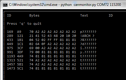
Link to the Github page of the author of this very useful script: https://github.com/alexandreblin/python-can-monitor
and the corresponding Arduino sketch: https://github.com/alexandreblin/arduino-can-reader
In my setup, the constants are:
// CS pin for CAN bus shield
const int CS_PIN = 9;
// CAN bus data rate
const byte CAN_SPEED = CAN_500KBPS;
We can see that there's only about 10 Can ID's in the protocol. Obviously, the 0x121 is used to send text on the display. As a CAN data frame is only 8 bytes and the display is 8 characters, I hoped that a single 0x121 frame could prints the entire text on the display, but it is not easy as that.
Each time text changes, four 0x121 frames are send... More on that later.
Discussions
Become a Hackaday.io Member
Create an account to leave a comment. Already have an account? Log In.