 Litan Virgil
Hardware
Initial design
Note: Since the time I wrote this I continuously improved the design, so in a few places I will discus the initial decision versus current version. Also, if you check out the repository, there'll be the current state of the project.
So, first things first: I needed a datasheet of the VFD. Easy, right? Well, not really. After lots and lots of research I was able to find a blog post about those tubes and the related pinout . It was sufficient in order to understand what is needed, namely 20V voltage supply for the grid and segments and 1,5V for the filament.
Furthermore, in order to make it as easy as possible I chose an ATmega328 to play the role of the brain for this system. In order to keep the time accurate and preserve it throughout power-offs, an RTC with a backup battery was needed.
As the MCU doesn't have enough pins to drive each segment of each tube I decided to apply the widely-known technique of multiplexing. In order to do this, a transistor has to be added for each tube to turn it on and off, besides the transistors that drive the segments - but we`ll get to the driver design later on.
I wanted a minimal user interface so I decided that 1 push-button should be enough to swipe through the functional modes, namely hour and minute display, day and month display or simply year display. Also, a buzzer should be useful for... well, I don`t really know yet, but I will surely find its utility on the long run. Alarms, maybe? Also, given the fact that it's the IoT era, the UART port of the MCU should remain accessible if I later decide to incorporate Bluetooth / WiFi / GPS into the project.
Lastly, I wanted to design 2 custom PCBs which ended up stacked inside the final product (in order to obtain a more compact and retro-looking clock).
So, the main components of the project are:
- 4 tubes and their corresponding drivers;
- 1,5V power supply;
- 20V power supply;
- 5V power supply (for the MCU);
- RTC chip and backup battery;
- ATmega328 with ISP connector;
- Buzzer driver.
The tubes and their drivers
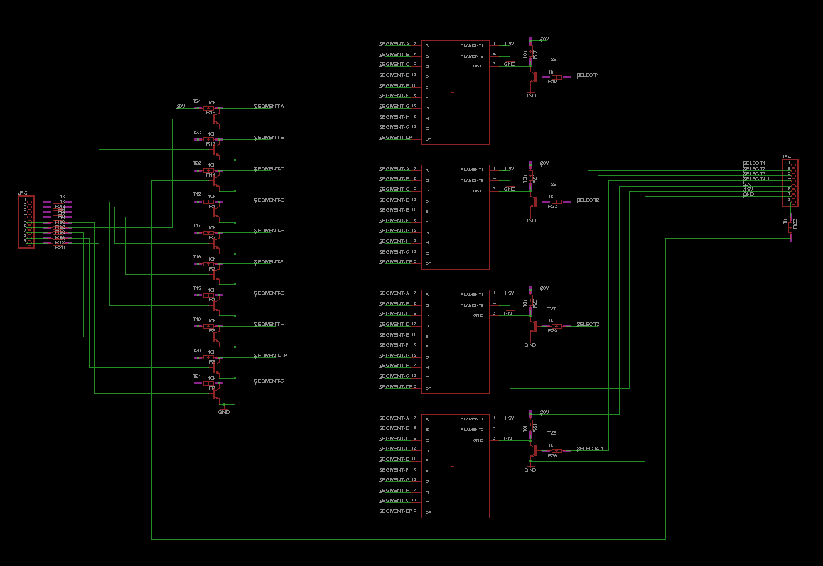
I decided to use basic NPN transistors in order to pull down the pins of the segments that would be otherwise pulled up by the 10K pull-up resistor. Also, a 1K resistor was needed between the MCU pin and the base of the bipolar transistor. The same strategy was used to drive the grid pin of each tube that acts like an enable pin. All corespondent segment pins are connected to be multiplexed (a more detailed view, use the link to the project repo).
The first issue with those "well-documented" tubes it was that there was no footprint to be imported in Eagle. So what now? I had to make it by myself. I measured the size of the tube and drew the shape of it and then I had to place all 13 pads in a circle, equally spread-out. After trying to do this by hand I remembered that, hey, I`m a programmer, so I wrote a short C program that wold generate a script for Eagle that would place all the pads correctly. Here it is:
#include <stdio.h>
#include <math.h>
int main(void){
    float i;
    for (i = 0; i < 3.141592 * 2; i += 3.141592 * 2 / 13) {
        printf("pad (%f %f); ", sin(i) * 3.1f, cos(i) * 3.1f);
    }
    return (0);
}
After putting all the pieces together, I obtained the PCB responsible for holding and driving the VFDs:
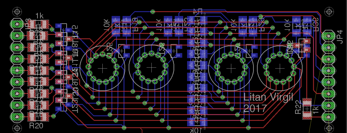
You can also see the pins that interconnect the boards on both far left and far right of the design.
Power supplies
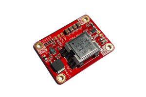
Switching
In order to provide 1,5V (1,5V turned out to be to much, as you can see in this video, the filaments turn red-hot) and 20V I needed a buck converter and a boost converter. Regarding the design...
Read more »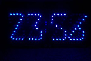
 Ken Yap
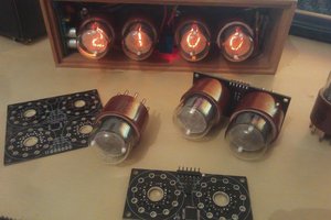
 Thomas Flayols
 Tony
Tony