 Frank Buss
This program for the PIC12LF1572 implements a monoflop with a fixed output time. It detects a falling edge on RA0 and then outputs a one second falling pulse on all other pins, after rising edge on RA0 (max 1.1 seconds, if the input pulse is shorter than 100 ms). Measured behaviour:
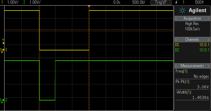
The green trace is the input signal and the yellow trace is the output signal.
It uses the low power sleep mode of the PIC12LF1572. The datasheet says it needs 20 nA at 1.8 V, I measured 13.3 nA at 3.3 V. A CR2032 coin cell battery would last many years with this low power consumption.
The internal pullup for the PIC at RA0 is about 50 kOhm. Without the pullup it needs about 2.5 uA when running with 31 kHz.
Full source code:
// monoflop: falling edge on RA0 creates
// a one second falling pulse on all output pins after rising edge
// (max 1.1 seconds, if the input pulse is shorter than 100 ms)
// PIC12F1572 Configuration Bit Settings
// 'C' source line config statements
// CONFIG1
#pragma config FOSC = INTOSC    //  (INTOSC oscillator; I/O function on CLKIN pin)
#pragma config WDTE = OFF       // Watchdog Timer Enable (WDT disabled)
#pragma config PWRTE = OFF      // Power-up Timer Enable (PWRT disabled)
#pragma config MCLRE = OFF      // MCLR Pin Function Select (MCLR/VPP pin function is digital input)
#pragma config CP = OFF         // Flash Program Memory Code Protection (Program memory code protection is disabled)
#pragma config BOREN = OFF      // Brown-out Reset Enable (Brown-out Reset disabled)
#pragma config CLKOUTEN = OFF   // Clock Out Enable (CLKOUT function is disabled. I/O or oscillator function on the CLKOUT pin)
// CONFIG2
#pragma config WRT = OFF        // Flash Memory Self-Write Protection (Write protection off)
#pragma config PLLEN = OFF      // PLL Enable (4x PLL disabled)
#pragma config STVREN = ON      // Stack Overflow/Underflow Reset Enable (Stack Overflow or Underflow will cause a Reset)
#pragma config BORV = LO        // Brown-out Reset Voltage Selection (Brown-out Reset Voltage (Vbor), low trip point selected.)
#pragma config LPBOREN = OFF    // Low Power Brown-out Reset enable bit (LPBOR is disabled)
#pragma config LVP = ON         // Low-Voltage Programming Enable (High-voltage on MCLR/VPP must be used for programming)
#define _XTAL_FREQ 31000
#include <xc.h>
void interrupt ISR(void)
{
    // set all output pins to 0
    PORTA = 0;
    // wait 100 ms to debounce the input signal
    __delay_ms(100);

    // wait until rising edge
    while ((PORTA & 1) == 0);
    // wait a second
    __delay_ms(1000);

    // set all output pins to back to 1
    PORTA = 0xff;
    // clear interrupt flags
    IOCAF = 0;
}
int main()
{
    // internal oscillator 31 kHz and PLL disabled (resulting in 31 kHz clock)
    OSCCON = 0;

    // all I/O pins are configured as digital
    ANSELA = 0;
    // disable ADC module
    ADCON0 = 0;
    // initial value of port A bits
    PORTA = 0xff;
    // pin RA0 and RA3 configured as inputs, other as outputs
    TRISA = 0b00001001;

    // set pull-up on RA0 and RA3
    WPUA = 0b00001001;
    OPTION_REG = 0x7f;
    // enable pin interrupts for RA0 on falling edge
    IOCAN = 1;

    // clear interrupt flags
    IOCAF = 0;
    // set IOCIE bit for pin interrupts and global interrupt enable bit
    INTCON = 0b10001000;
    // go to sleep mode in a loop, because the interrupt wakes it up
    while (1) {
        SLEEP();
    }
    return 0;
}
 UTSOURCE
 Bruce Land
 Klaus Dormann
 johnowhitaker