 Marius Taciuc
Introduction:
When I first started designing this clock I had in mind that I wanted to use some LED lights that are not too bright, but in the same time, they can be seen during daylight or direct sun exposure.
Challenge:
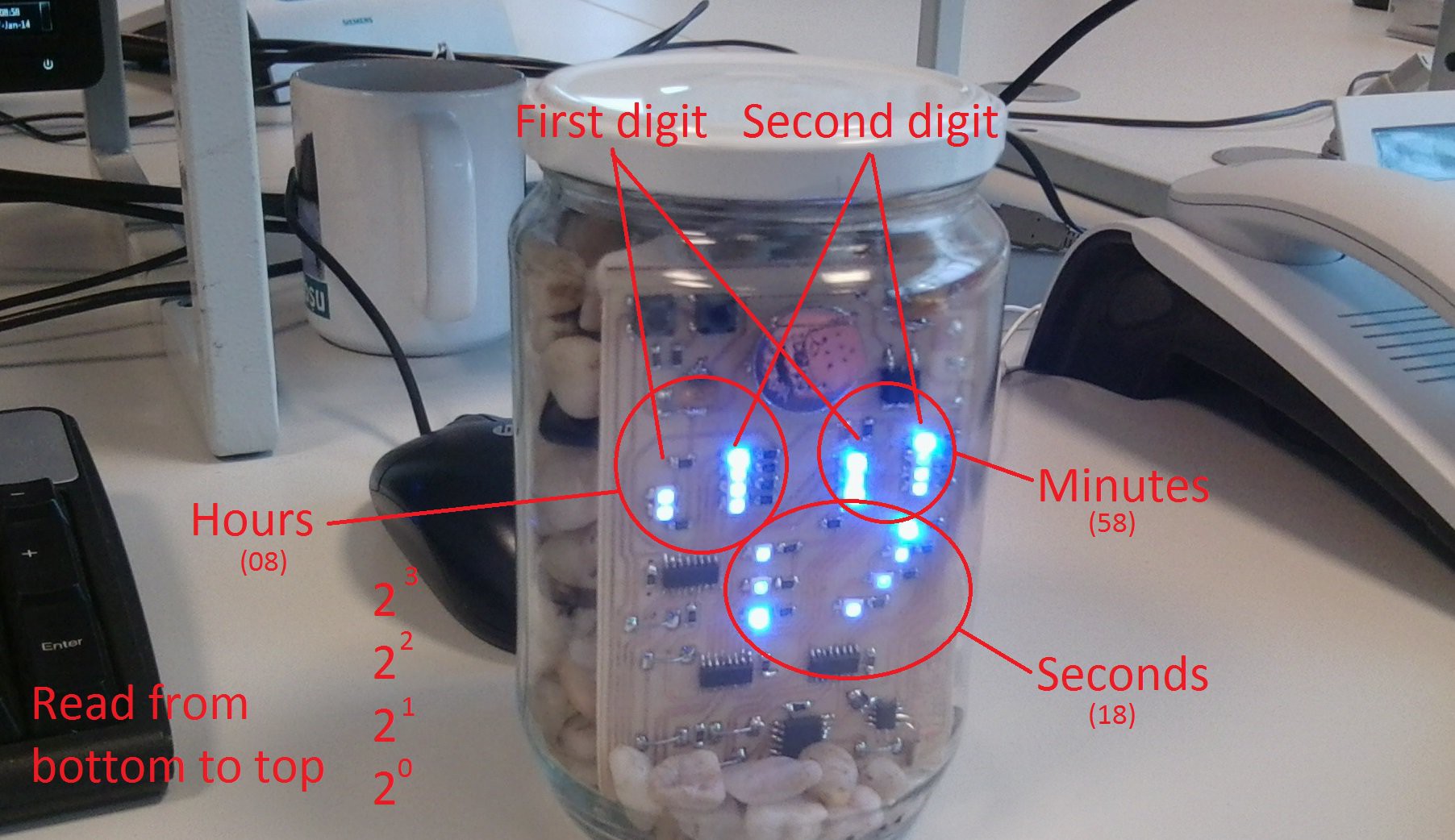
There was another problem with reading the clock at night. If during the night, some of the LEDs are turned off, how are you able to read the binary string? I mean, it is OK if the 2^3 LED is turned off and all the others are turned on. in this case you can still assume is displaying 7, but what if the 2^0, 2^2 and 2^3 are turned off and only 2^1 is turned on in the digit string. how was I about tho know what it displays, because in the dark you are not able to tell witch LED is it.
Solution:
The solution was to control the LEDs using a PWM and to make the inactive ones a bit dimmed compared to the active ones.
In your case:
I realize you are going to use a different type of LED if you are going to replicate this design and you will need to recalculate the serial SMD resistors according to your needs. Keep in mind that his is not a multiplexed display and the LEDs are powered continuously and not intermittently. Yes, the LEDs have a PWM, but the entire display doesn't have a refresh rate. Here is a video I made some time ago explaining how to calculate the LED serial resistor:
Another solution for regulating the intensity of the LEDs according to the outside light intensity, would be to connect a photoresistor voltage divider to one of the MCU A/D channels and regulate the PWM internally. (you can always replace the MCU with a PIC16F819 - it has the same pinout and it has an A/D converter module)

 Robert Gill
 davedarko
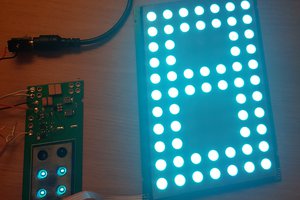
 makufelis-xyz
 Jan
Jan
Topic about the power supply and the 7805.
You might be wondering why I placed a 7805 linear regulator on the board if I was planning to always power it from the very steady USB voltage.
The answer it's simple. Because I thought that someone might want to connect it to a cheap chinese ~240 to 5V USB charger and that particular cheap device has a high ripple switching power supply inside. Usually these USB cheap adapters, are set to an effective voltage of 5V and could have spikes or ripples of +-0.5V