 Carlos Garcia Saura
Spark detectors, as well as Geiger counters, require of very high voltages to operate. These must be avoided in order to achieve a simple detector circuit. Dropping the requirement for a high voltage would be more safe and need less power to operate.
Ionization chambers are the solution to this problem. Rather than generating sparks or discharge pulses, they use a low voltage to separate the ions created when high energy particles interact with a gas (air, in our case). These tiny ion currents are then measured with a very simple amplifier circuit.
There is a long history of detectors based on ion chambers. They have already been used in professional radiation monitoring equipment, and moreover, many hobbyists have come up with very simple designs that can be built at home. Check out this website to learn more about DIY ion chamber radiation detectors: http://www.techlib.com/science/ion.html
The simplicity and high sensitivity of ion chamber detectors makes them ideally suited for this project.
Our first iteration used the same layout as the "spark detector attempt" we showed in log entry 3.
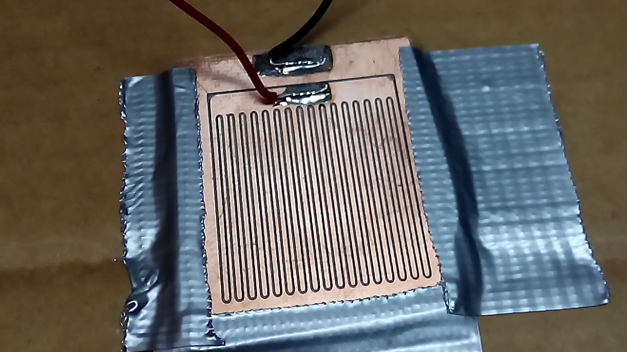 Instead of applying a high voltage that causes sparks, using it as a ionization chamber means we applied a low potential (12V) and measured the tiny ion currents induced by radiation.
This design did NOT work because there is only a tiny volume of air between the electrodes, and plenty of leakage between the "finger plates" as contact surfaces are large.
The second iteration started as a very ugly prototype that we are not going to mention again:
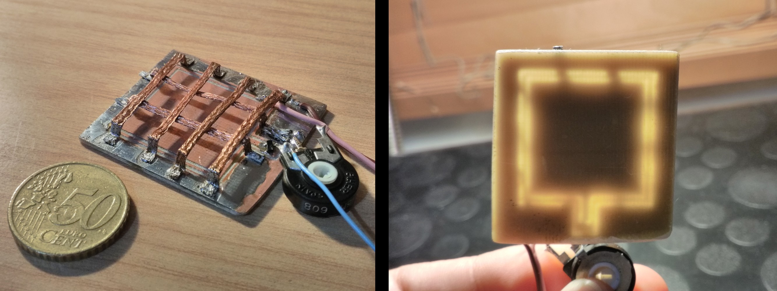 Let's focus on the "pretty" prototypes instead.
The idea behind the new design is as follows:
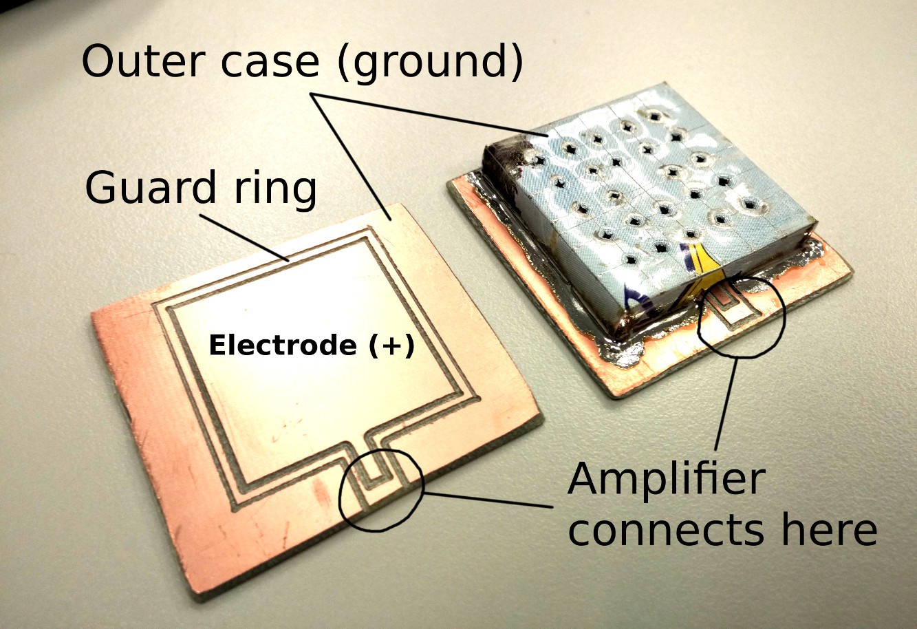 An electric field is created between the electrode plate and the outer case. The ionized air is attracted by the electrodes, and a current can be measured. These ion-induced currents are proportional to the amount of radiation present.
The interesting thing about this approach is that it uses a printed circuit board as part of the sensing element. This is the key to reduce manufacture costs.
The third iteration was built with a commercially available circuit shield. It also incorporated a ground plane behind the electrode to reduce the effect of static electricity over the measurement.
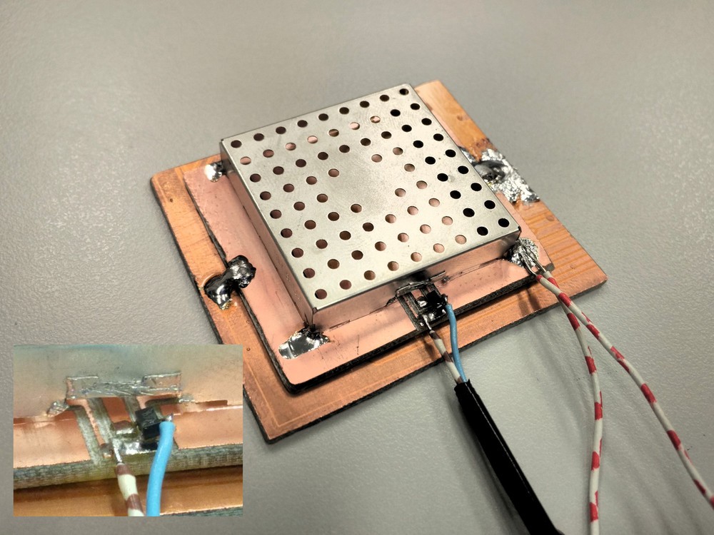 This prototype actually worked!!
Bringing a radiation source near the detector generated a voltage on the multimeter:
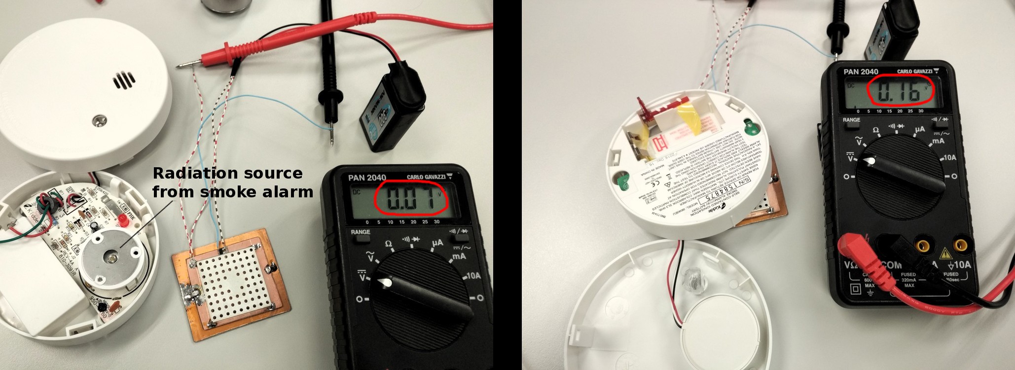 The first success was very rewarding - it proved that we were on the right track!
For the next log entry we will review the amplifier circuit and the long term effect of temperature in the detector.
If you like this project, be sure to click the follow button to not miss any updates!
Discussions
Become a Hackaday.io Member
Create an account to leave a comment. Already have an account? Log In.