 Craig Watson
One important aspect of the ESP32 code that wasn't mentioned in the previous log concerns the analog <-> digital conversion.
Long-term, the idea is to integrate pressure regulators into the design of the PCB, but for now we use commercial ones, which require an analog voltage between 0 and 5 volts for the setpoint, and indicate the current measured pressure in the same way.
This was mostly important for the hardware design, as I explained in the selection of PCB components, and the PCB design. However, there were also software consequences.
It turns out that the ESP32 ADC isn't quite linear. Same goes for the DAC, especially given that the output is amplified. Therefore, some calibration was necessary.
For the ADC part, this consisted simply in connecting a variable power supply to the ADC pins, applying voltages between 0 and 5V (in 0.5V increments), and outputting the value of analogRead() to serial using a short sketch I wrote for this purpose. I wrote down the values and plotted them in Excel, which gave the following results:
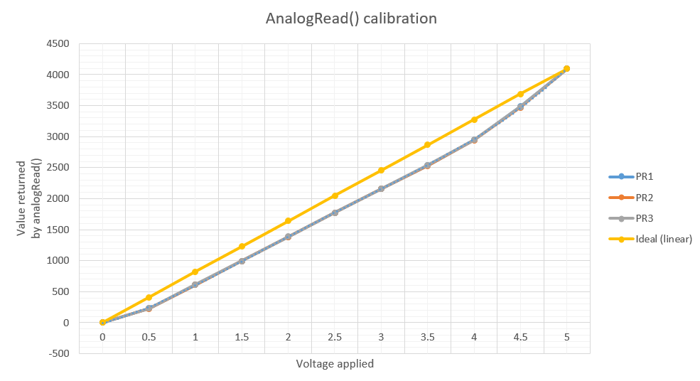
PR1, PR2 and PR3 are the three ADC pins; the values were virtually identical for all three.
To correct the error, I fit a polynomial to these values, and this polynomial is used when reading the current pressure:
uint8_t PressureController::getValue()
{
    int val = analogRead(mMeasurementPin);
    double x = val;
    double y = -3e-12*pow(x, 3) - 7e-10*pow(x, 2) + 0.0003*x + 0.0169;
    mMeasuredValue = std::min(255, std::max(0, int(round(y*UINT8_MAX))));
    return mMeasuredValue;
}
This actually works pretty well, and the measured value is now close enough to the actual value to be usable.
For the DAC part, the process was similar, with a short sketch that read a value sent over serial and applied that voltage to all three analog outputs.
The ESP32 doesn't yet have an implementation of Arduino's analogWrite() function. Instead, it has dacWrite, for the two channels of the built-in DAC, and ledCWrite, which is pretty much identical to Arduino's analogWrite() and drives the PWM output.
The error was much smaller than with the ADC:
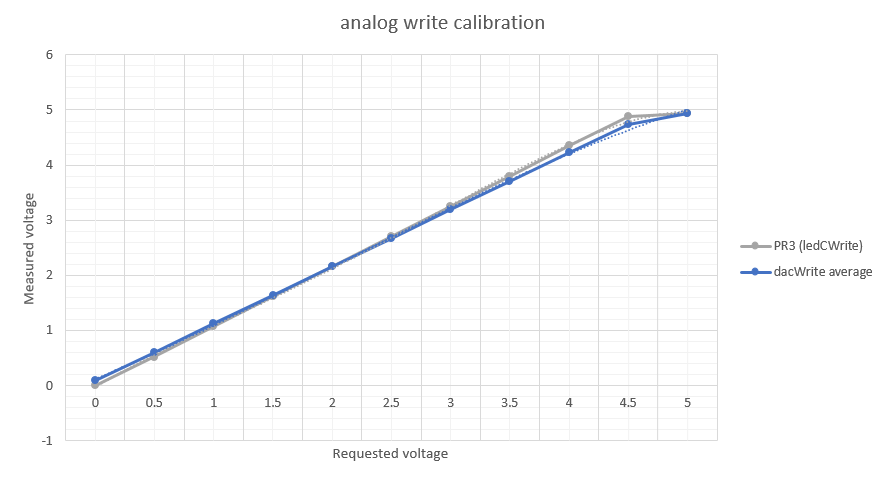
Still, it's enough to warrant some correction, so the PressureController::setValue function was modified to correct the output, again based on a polynomial fit done in Excel.
The complete spreadsheet, including values post-correction, are available on the Github repository, here.
Discussions
Become a Hackaday.io Member
Create an account to leave a comment. Already have an account? Log In.