 Bruno Laurencich
As I said, it was time to make a second version of the PCB in order to be able to build a complete body suit. I’ve called it “K-Ceptor” (Kinetic perCEPTOR).
The changes are detailed on the previous log entry, and listed here:
- Changed the LSM9DS0 for the LSM9DS1
- Added an address translator and removed multiplexer
- RJ-12 connector for both input and output (or optionally solder a regular 2,45mm header)
- An EEPROM memory
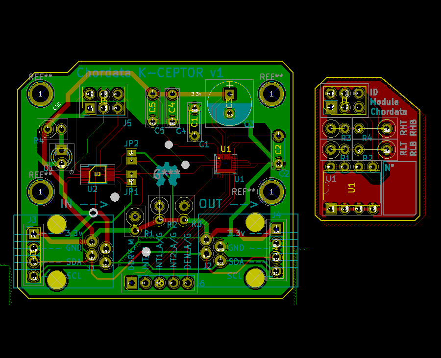
One thing that I hadn’t planned for (it came out while I was making this new pcb) was to arrange some of the components on a separate board: the “id_module”.
This module is a tiny, one-layered pcb, containing the EEPROM, some resistors to setup the translation value of the LTC4316 (i2c address translator).
This separation allows for greater flexibility and hardware resources reutilization. For example, suppose some user has a complete suit and, at some point, he is using it for two different activities taking place in different environments, namely: a capture for an animation performed outdoors and the rehearsals of a live performance in a theater. Since the electromagnetic interference on each location is completely different, the ideal would be to perform a calibration* on each sensor at least once for each place. Having a duplicate set of cheap id_modules would allow the user to easily apply the corresponding calibration before each use.
(*) again: I'm talking about the sensor calibration, not to be confused with the pose calibration which should be performed before every capture.
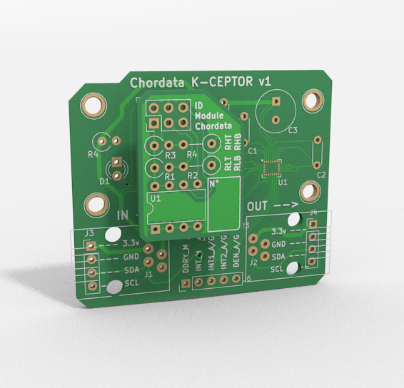
A render of the id_module stacked in position, on top of the K-Ceptor.
Discussions
Become a Hackaday.io Member
Create an account to leave a comment. Already have an account? Log In.