 Nikos
NikosA while ago I got a small batch of the second prototype's PCBs (many thanks to Zequing of Makerfabs).
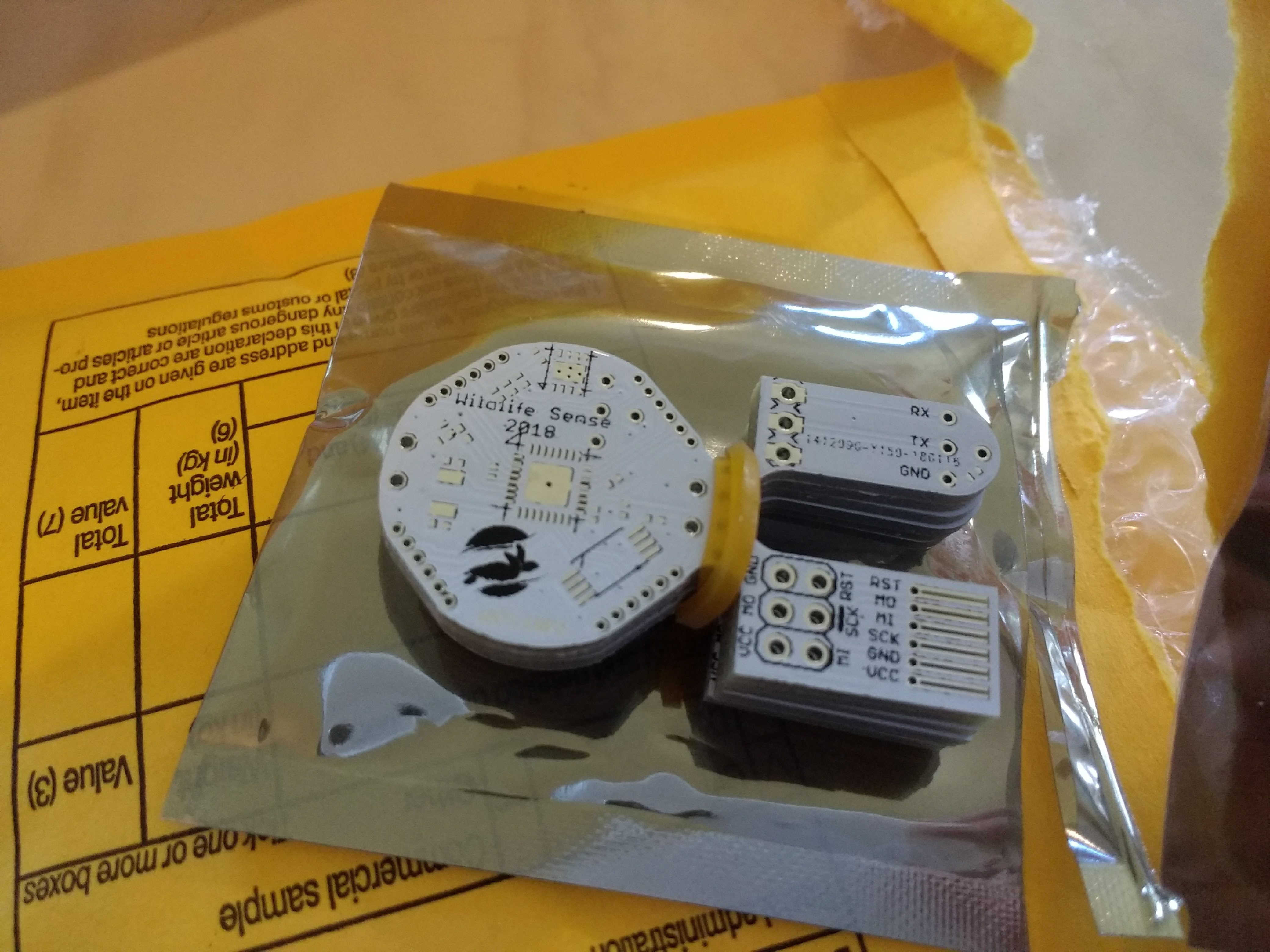
This version was a special Gerber I made to include the temperature logger's board (left), an AVR in-system programming connector adapter (bottom right), and a uart connector meant to be used with surface-mount spring-loaded connectors (top right).
Changes between prototype 1 and prototype 2
The main difference between the first and the second prototype designs is that the uart connector includes one more line, which is only used to short a pin to ground so the firmware knows when it's connected and can initiate a transaction. I don't even use an interrupt for that; the firmware just checks whether that pin is high (unconnected) or low (connected) every time it's woken up by the real-time counter. This scheme is a bit boring but saves quite a bit of power.
This design can use both the surface-mount and the through-hole versions of the CR2032 battery holder by Linx. This allows me to use already-purchased surface-mount uints, but in the future I'd prefer the through-hole because of added mechanical stressed caused by pressing the battery holder to hold the device.
Other changes include a change in the LED's location and the exposure of the I2C lines on the headers around the PCB.
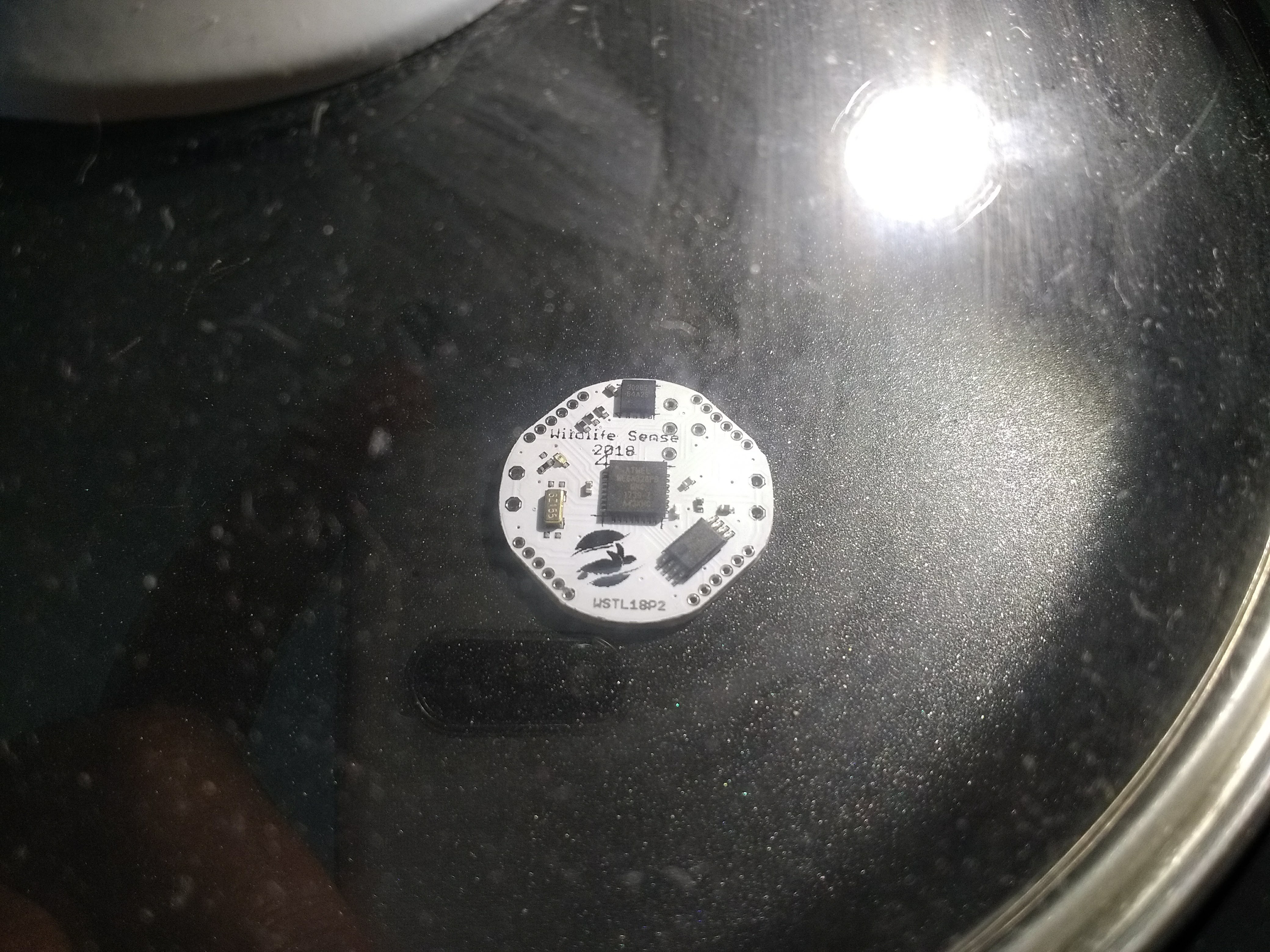
I also changed every component's stencil footprint. I use a steel stencil, and the first prototype had lots of solder knees and bridges. The second prototype, with a stencil opening of half the area for each pad, looks much better with no bridges at all. Everything worked on the first attempt. Below is the first unit cooking on the skillet.
Connecting to a PC
Although I added the uart connectors to the design, I haven't actually used them because I didn't add the spring-loaded smd connectors needed to my last order. Instead, I used a piece of stripboard and some generic pogo-pins, along with a 3.3V USB to uart device using FTDI's FT232. In the (not so distant) future, I plan to design a usb-to-serial board complete with pogo pins that you can hold like a pen.
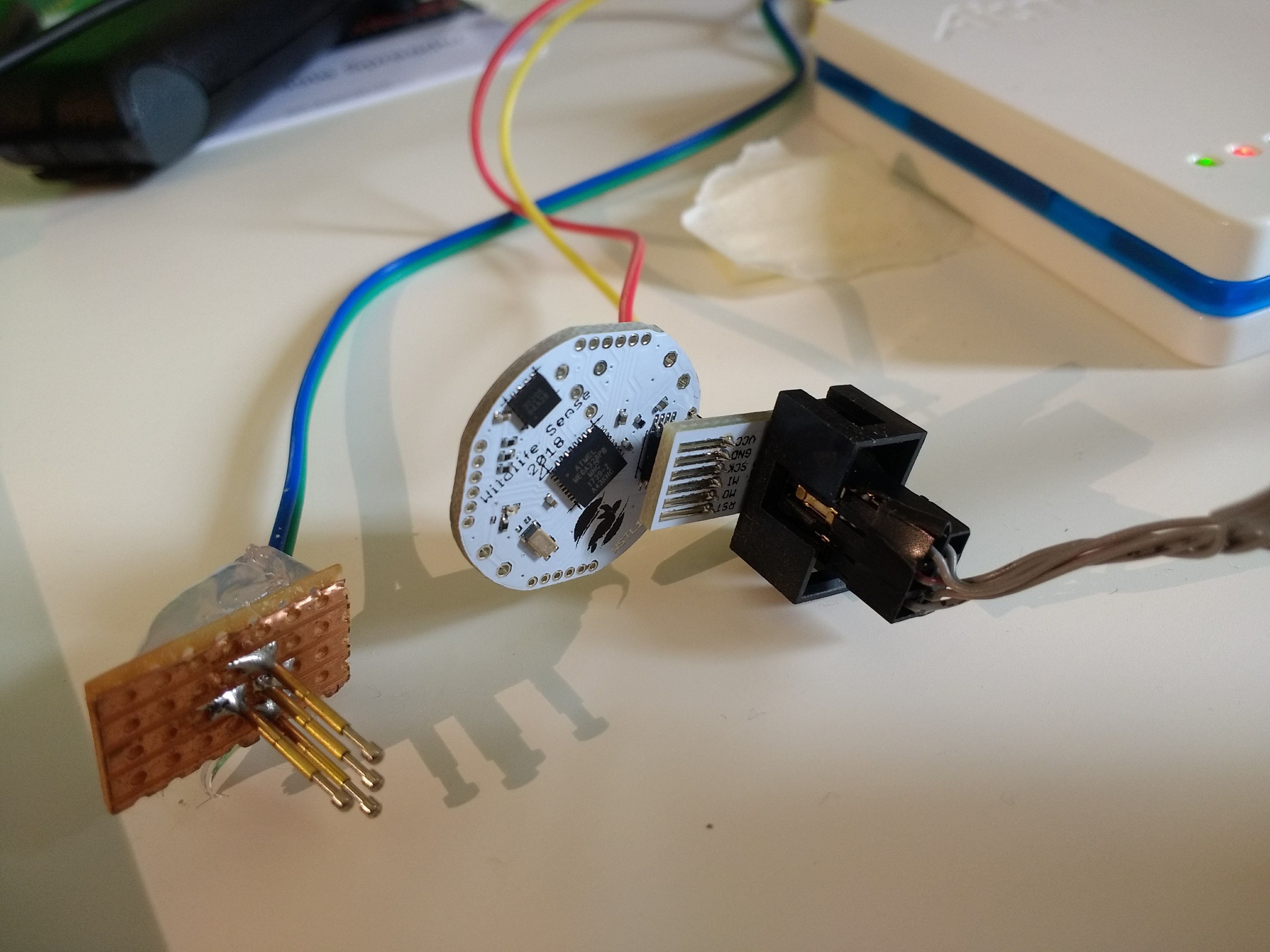
For now I'm using the serial adaptor's 3.3V output during firmware development.
Discussions
Become a Hackaday.io Member
Create an account to leave a comment. Already have an account? Log In.