 doctek
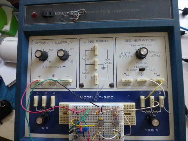
Eager to start designing a first version of the Lock In Amp Experiment Board (TM), I examined the sections that I wanted to include (noise source, clock filter, signal source, etc.) and realized that some level shifting and dual to single supply conversion would be required. No problem, I thought, that's what opamps are for, and I've used them before. But, as always, God lives in the details, and I hadn't worked closely with opamps for a while. So I dug out Horowitz and Hill, found my old opamp stash, grabbed the Heathkit ET-3100 Electronic Design Experimenter,googled relevant Apps Notes, and went at it. Building a few amplifiers, buffers, filters, and summers in both dual and single supply versions proved so instructive that I think I will change my approach to building an Experiment Board.
The new plan is to create some modules that will plug into a breadboard and connect in a flexible and easily changed manner. The ADA2200 will be one of these modules - it will mostly copy the design from the spectrophotometer and will expect to get the clock from a Teensy3.X and send signals to it. It should be easy to interface a different controller if desired. Two noise source modules are also planned. Their descriptions are included in the Files section. A filter to create a sine wave from the RCLK will be another module, as will a summing module and modules to create suitable input signals for the ADA2200. Other modules will be created as needed to support experiments. Obviously, these modules will be explained as they are created. The descriptions of the noise sources are in the Files section.
Discussions
Become a Hackaday.io Member
Create an account to leave a comment. Already have an account? Log In.