 Alastair Young
Instructions
- Place the display face down.
- Insert 2 x 7 header pins into positions 1-14, short end first. DO NOT SOLDER. On 16 pin displays, leave 15 & 16 open.
- Insert 2 single header pins into position A and K, short end first. DO NOT SOLDER.
- Place the adapter board on the pins. Display pin 1 to board pin 1.
- There are two positions for A and K - move the single pins around for the best fit with your display - there appears to be no standard locations for these on the displays.
- Solder the headers to the adapter board. DO NOT SOLDER TO THE DISPLAY.
- Lift the adapter board off the display.
- Trim off the long ends of the header pins with wire cutters. Eye protection is advised - those things fly!
- Insert the I2C module into the adapter board - on the other side from where you had the display. The GND pin on the I2C module is closest to the 14-pin header. Look at the picture.
- Solder 1 pin on the I2C module, then straighten it up. Then solder the other 15 pins.
- Trim off the long ends of the header pins with wire cutters.
- Position the display back on its headers.
- Solder the 14 pins to the display.


 SimonXi
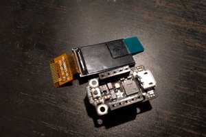
 deʃhipu
 Navarre
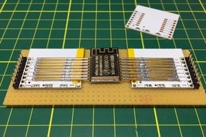
 evgeny.zislis
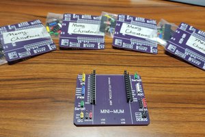
Thanks Dave, I only had the mandatory OSHPark three to start with. Two built into the demo/test units for 14 pin and 16 pin types to verify the A/K pin alignment. I'll order up a proper batch, should be in in a coupla weeks.