 deʃhipu
A small board, shaped like the CircuitPython's mascot snake, containing a minimal CircuitPython development board — pretty much just the microcontroller, regulator and USB socket.

Already have an account? Log in.
To make the experience fit your profile, pick a username and tell us what interests you.
A small board, shaped like the CircuitPython's mascot snake, containing a minimal CircuitPython development board — pretty much just the microcontroller, regulator and USB socket.
blinka.fzzFritzing design filex-fritzing-fzz - 45.98 kB - 10/20/2017 at 00:41 |
|
I finally got my hands on a vector version of the Blinka logo, and I immediately started working on the third version of the board. Of course the file was a horrible mess of spurious nodes, but after a couple of hours of cleaning it up, and some simple operations on the shapes, I have the basic layers ready:
This time the board outline is much simplified, to avoid problems with cutting it out. I realized that there is a fifth color that I didn't use — the raw FR4 board — so I used it here. I also made it much bigger this time — so that it fits in the 5×5cm square. That should give me enough space to fit the SAMD21, the coin cell battery, the power switch, and as many pads as I can route conveniently on a single side. I'm also considering just slapping a Trinket M0 on it — we will see.
I also fixed the short on the second version of the board, and uploaded the design to OSHPark here: https://oshpark.com/shared_projects/xMggaR8L
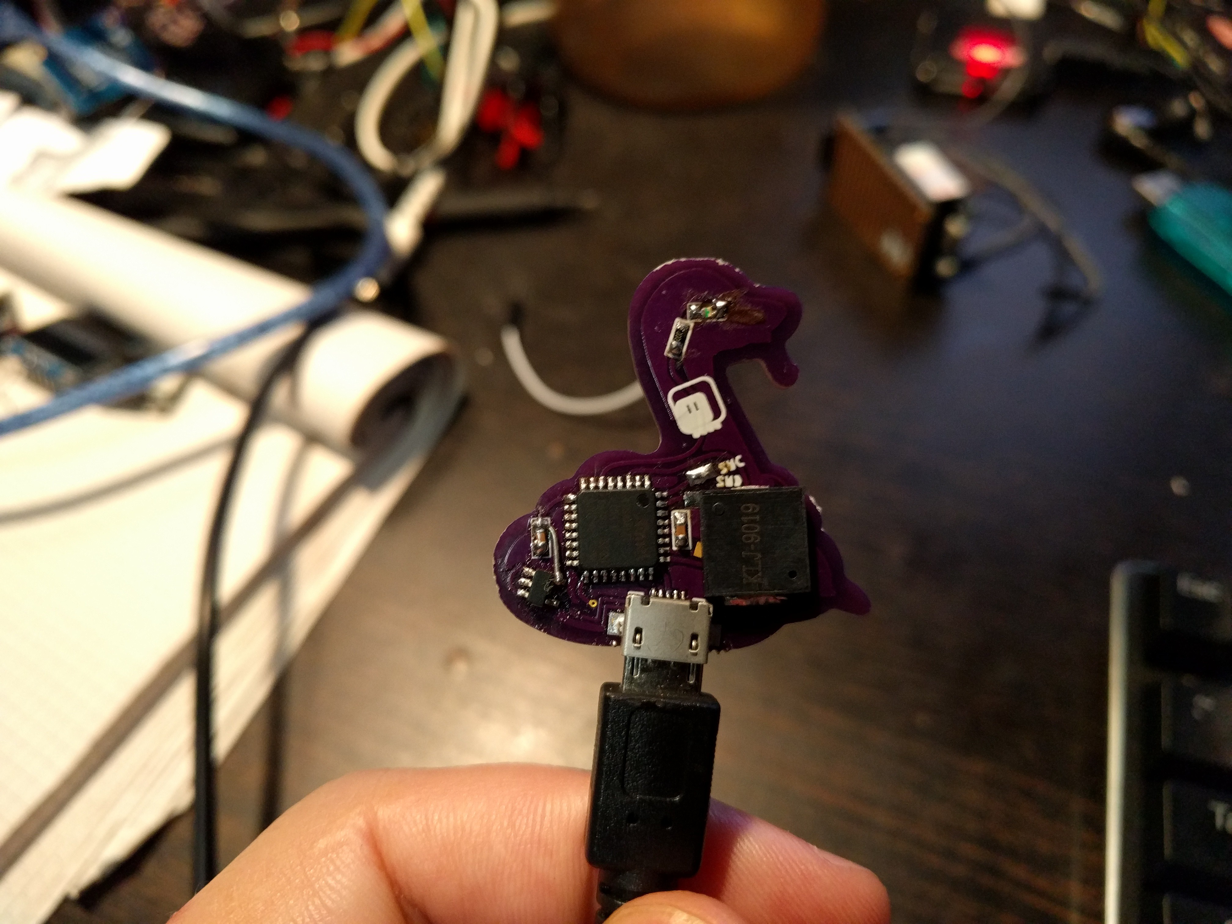
So I finally sat dawn, assembled the second version of Blinka, and flashed it with custom firmware. The firmware has only the pins I'm using, and has a number of modules removed (like analogio) to make room for touchio and audioio. Also usb_hid — so it can act as a keyboard or mouse. Two of blinka's segments are also touchpads.
In other news, I finally got a hold of the vector files for Blinka, so a bigger version with a coin cell on it is in the works (and I will probably enter it in the contest too).
This is the second PCB in a row that has its VCC connected directly to its GND. This time after the LDO, though, so I burned a couple of them before I realized.
On to the next version, I guess...
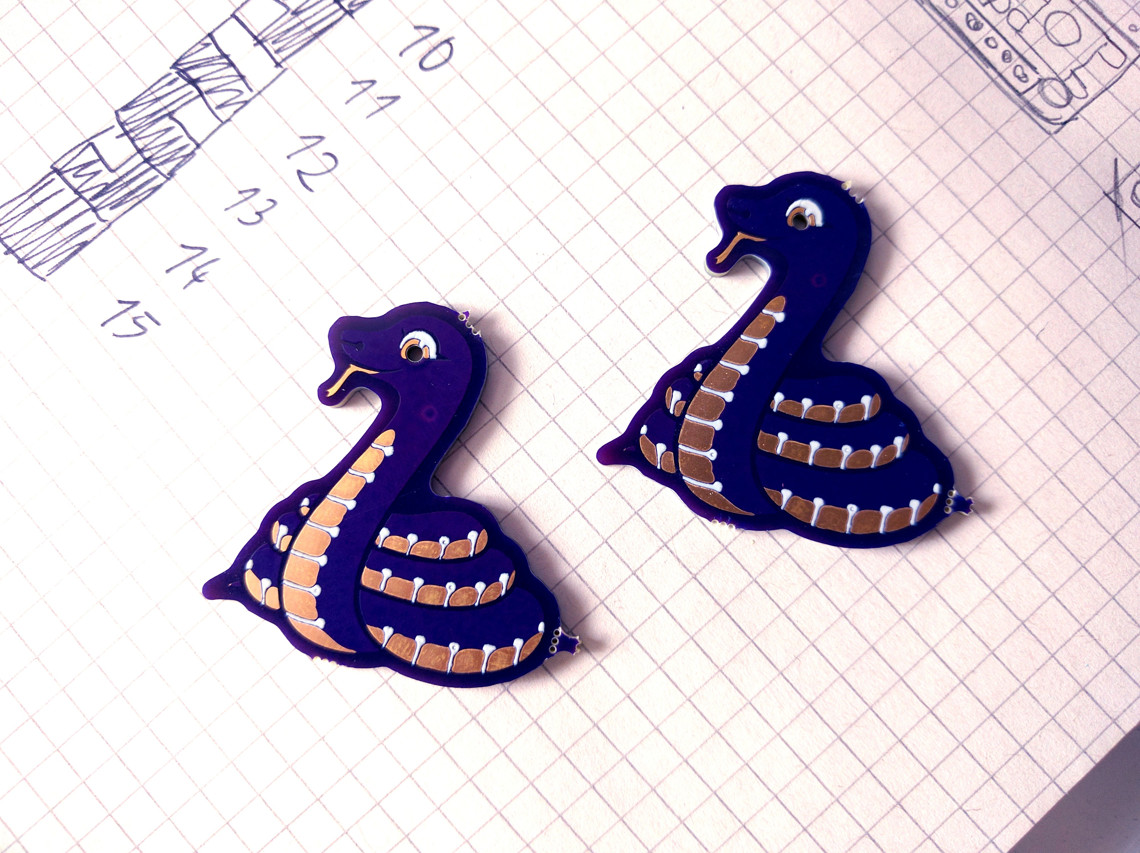
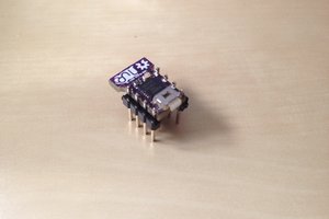
The second version arrived from @oshpark, and it seems that the neck is fixed. Also, the hole for the LED in the eye looks fine, and the vias that are buried under the solder mask and the silkscreen are practically invisible.
I don't know where that brighter violet circle on the neck comes from, but it's in the same place on both boards (for some reason I only received 2 from, not 3 boards).
I'm not assembling the circuit on the back just yet, because I ran out of parts for it — I will need more micro USB sockets.
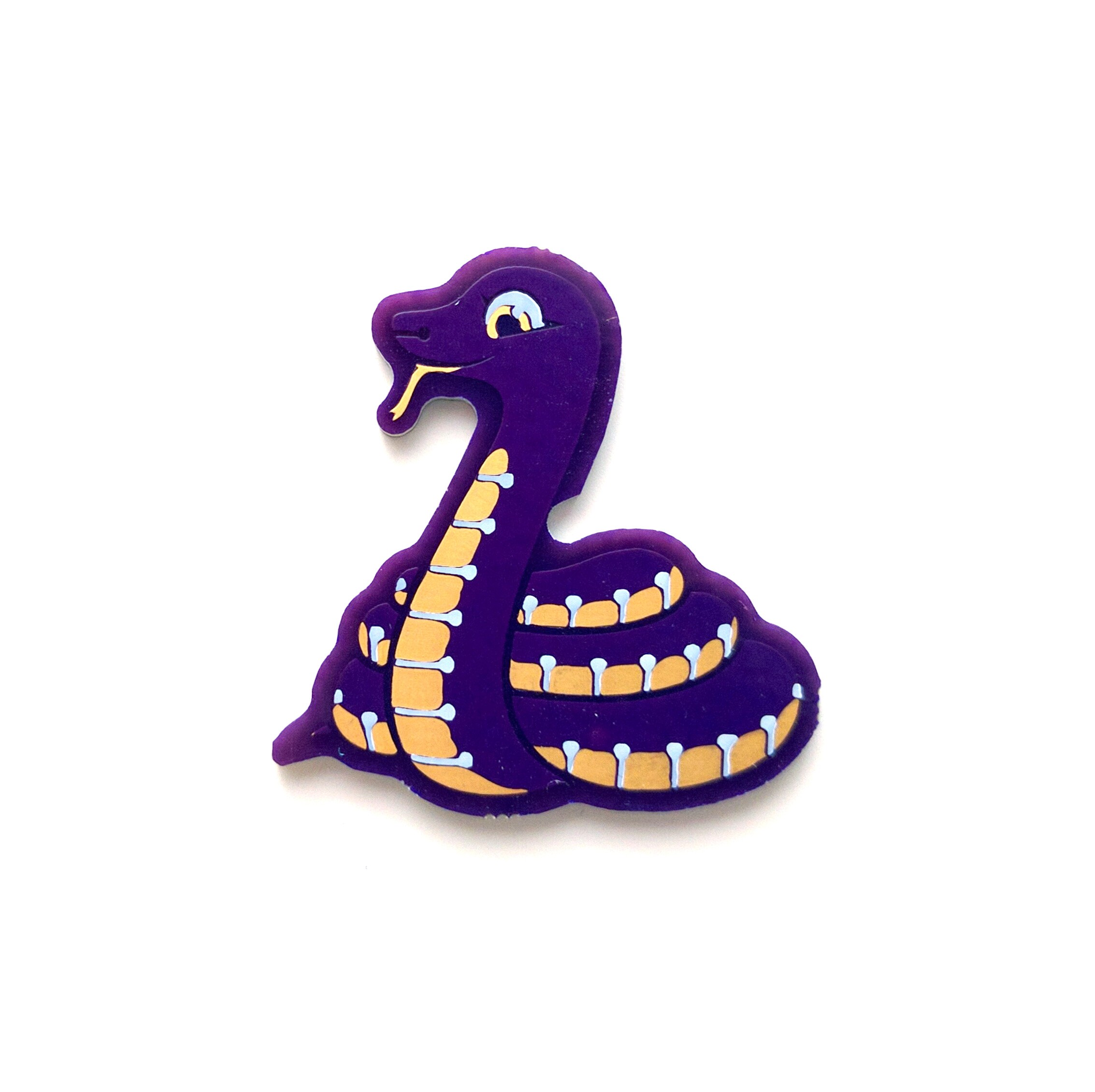
The boards arrived from OSHPark and they look great:
One thing that I need to fix is the corner at the back of the neck (do snakes have a neck?) — make it a bit smoother, so that the CNC tool has room for cutting it. By the way, now we know how large a tool OSHPark uses.


Thanks. Yeah, I figured as much, but only after I saw it — the second version has this fixed.
I wonder how hard it would be to include a check for this in the preview?

Yeah, I'm mostly after the serial console here. Though it occurred to me that I can still use the touch sensing on the pins — just touch the whole chip.

The large one is not connected, the small ones are for debugging pins. I was thinking about adding a row of pads along the neck for the pins, but then realized how hard it will be to route them on a single side, and got a sudden attack of laziness.
There is a cap after it. We will see how that works, in the worst case I will bodge an additional cap on there somewhere.

 Daniel Grießhaber
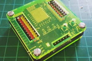
 davedarko
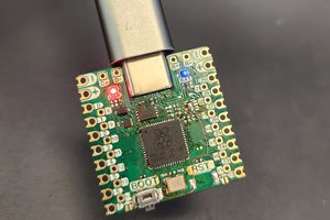
 Chris
Chris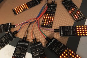
 Bob Coggeshall
Love the design!
FYI - the milling bit needs 68 mil clearance. For example, this octopus board was modified so that all the contours could accomodate at 68 mil circle (https://www.instagram.com/p/BYJSoLggk_P/?hl=e&taken-by=gsreynaga) and it came out good: https://www.instagram.com/p/BX9CUYLA1p9/?hl=e&taken-by=gsreynaga