 Jarrett
Back in February, I quickly soldered some components onto my board, and it didn't seem to work, and I suddenly got slammed with Actual Work That Matters, so I didn't investigate much further.
Recently, I finally got some spare time to do some digging.
I should mention, I designed this PCB in, like, November or something, so I don't remember the actual act of *designing it*, and this is just as much of a journey for me as it will be for you!
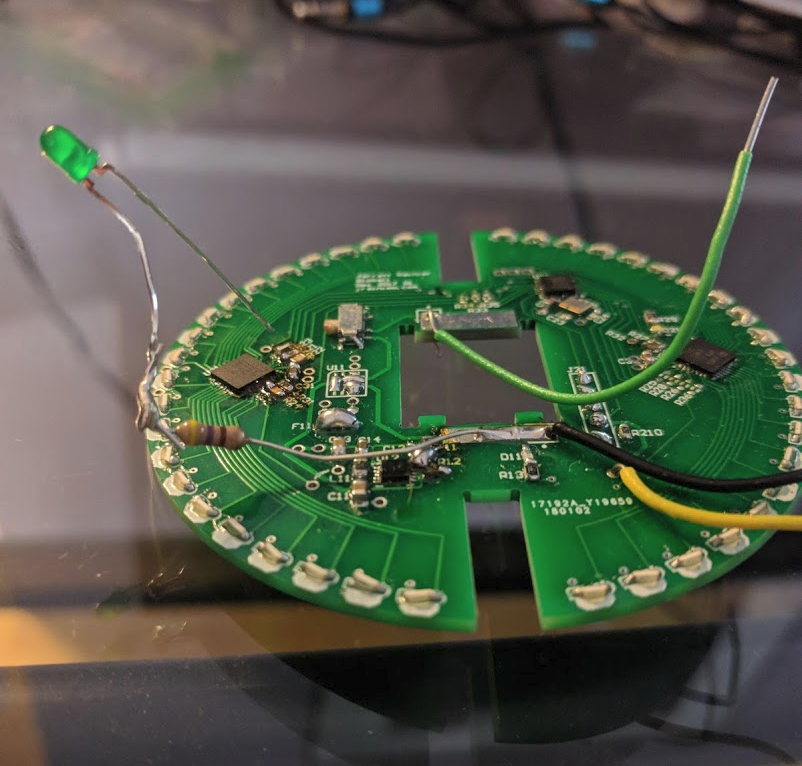
Skeeeetchy
There are three main sections of note:
- The power supply (currently bypassed) - we'll come back to this.
- The microcontroller, working!
- The LED control section.
The LED section, using the TLC5947, just doesn't turn on or respond to communication.
After probing around a little, I went back to the datasheet, and compared to my designs:
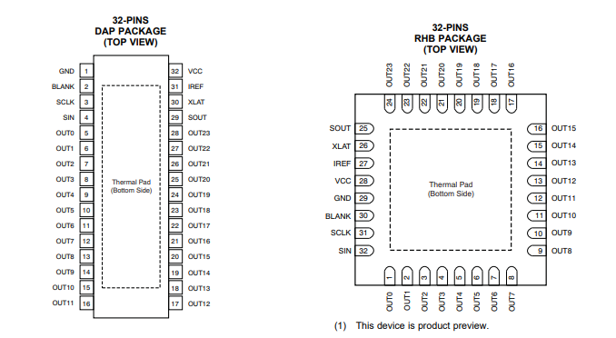
Hmmm, I'm already seeing something to watch out for. The pin numbers in the different packages are different.
My PCB:
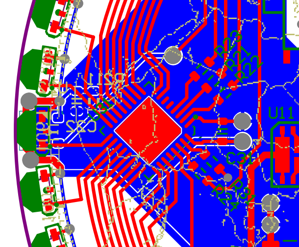
That's not good. The big red square in the centre of the image is U31, the LED driver IC. Just to the right of that, you can see C31, a bypass cap. These usually connect VCC to GND, and on this PCB, it is straddling pin 1 and pin 32.
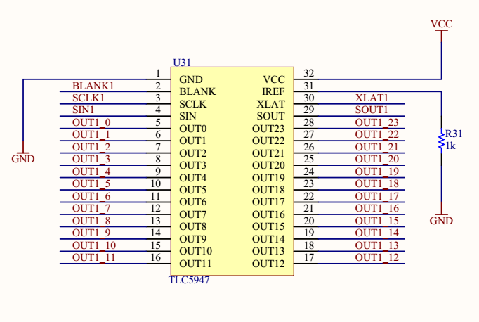
Yeah, that's how I hooked it up to my schematic. That's not good! As you can see from the datasheet screencap, those are not the proper VCC or GND pins, and everything else is shifted, too. Bodging this to work is tricky, too - The correct VCC pin is 28, that stub in the bottom right of my PCB.
It's tiiiiiny. One of those pins just to the left of R24.
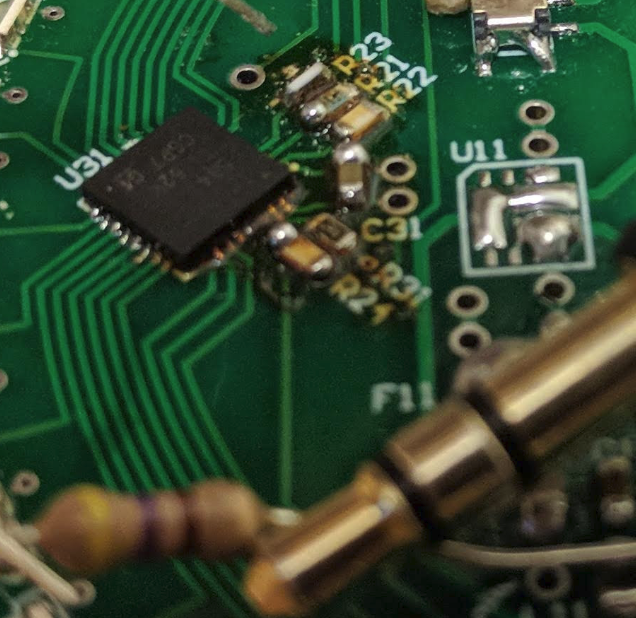
Shown here with a 3.5mm audio jack for scale, and the twice-reflowed burnt resistors.
I'm not sure just yet if I should continue bodging with a breakout board, or fix and send it off for manufacturing again. Leaning towards the latter, but if I had free time, I could totally lift off the chip, solder it onto a breakout board, and then solder point to point to the QFN pads.
Just to double check my microcontroller section, I wired up the external LED driver breakout board I have to some test points:
Works! Microcontroller portion is good.
Discussions
Become a Hackaday.io Member
Create an account to leave a comment. Already have an account? Log In.