 Jarrett
Here's a mock up of the PCB. It'll be spun axially by 3mm shafts on the top and bottom.
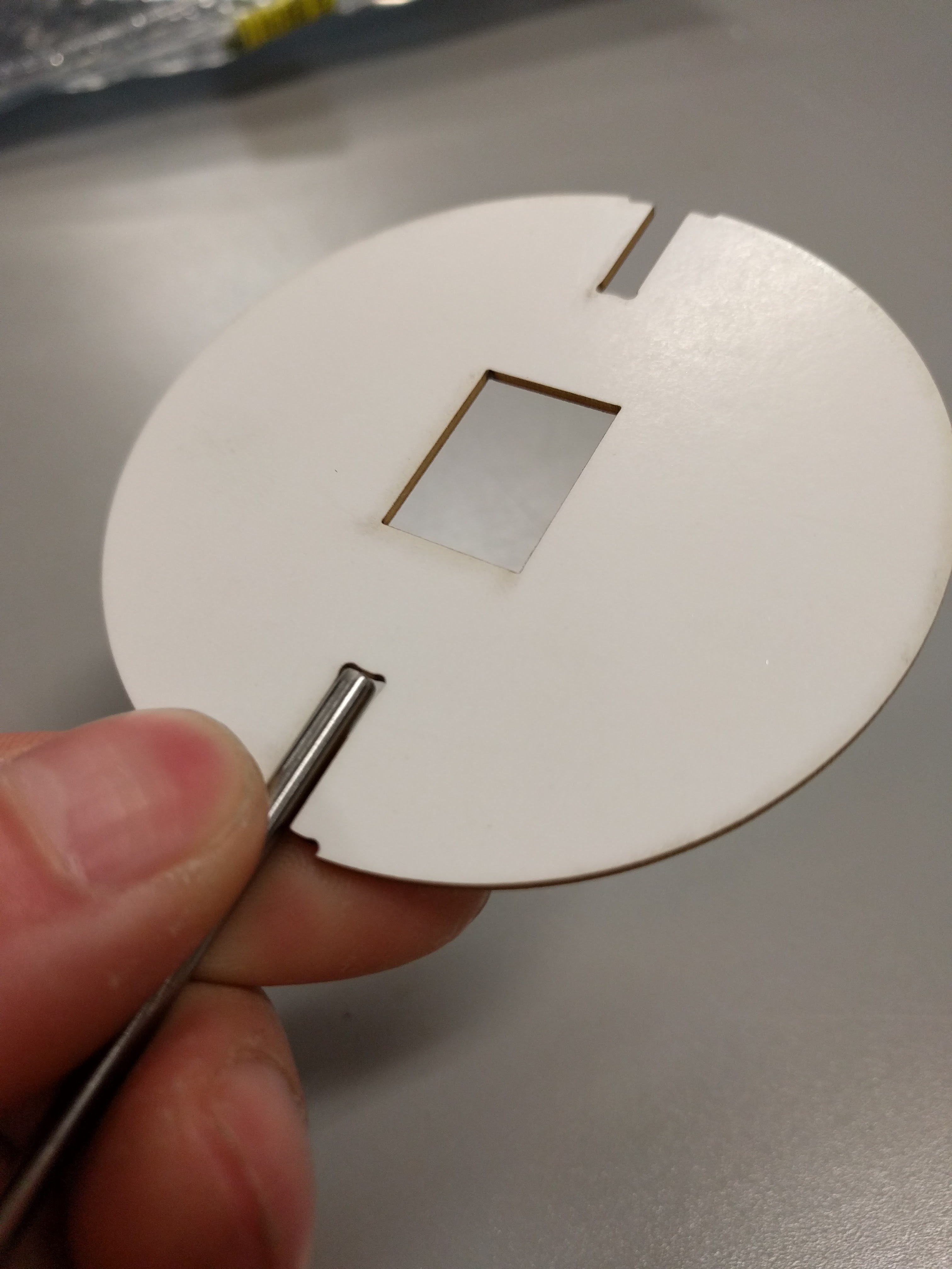
And herein lies the second question:
What's a good method for affixing the shafts to the PCB?
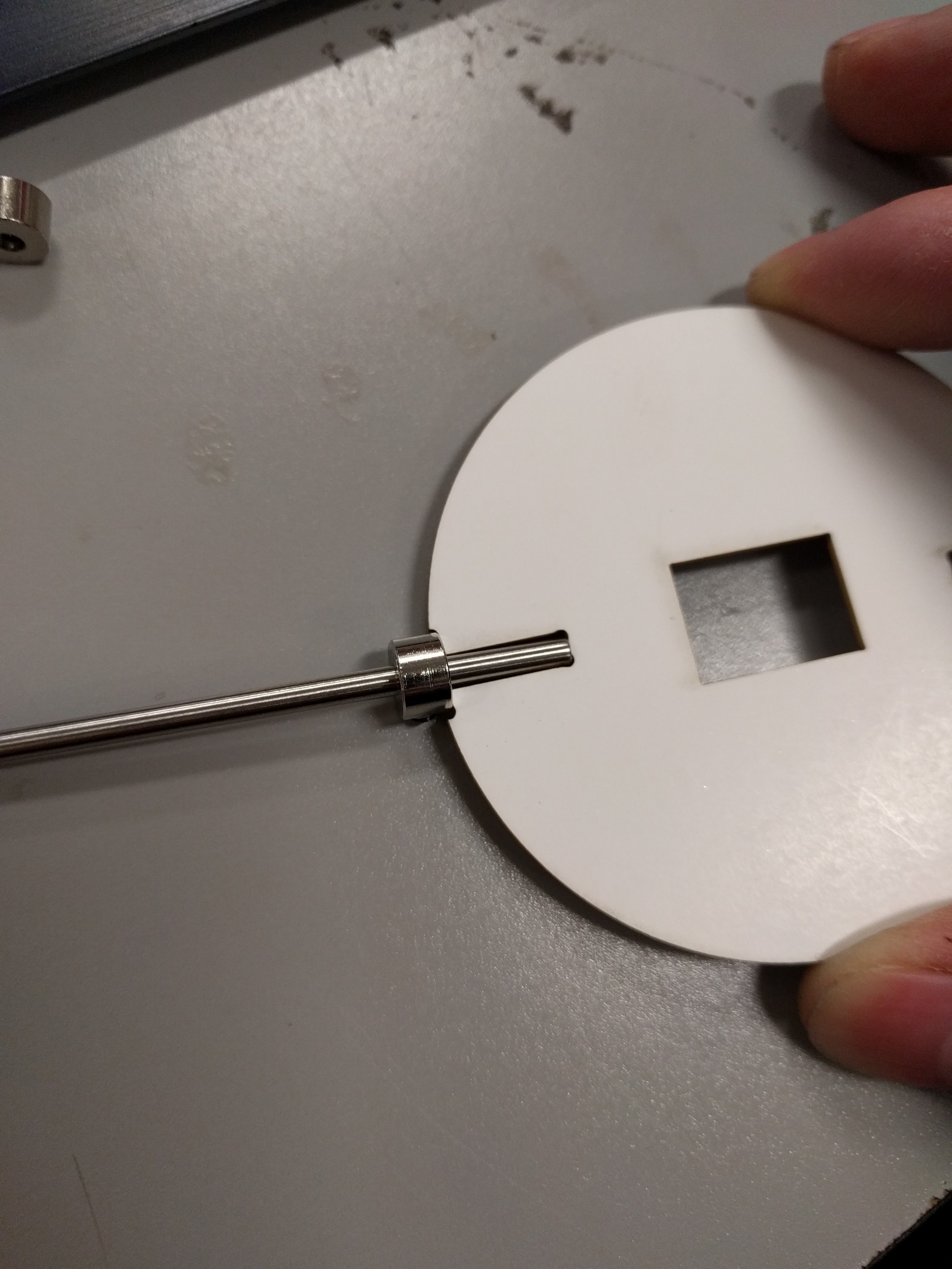
The current working plan is to use a shaft collar with a 1.6mm thick slit carved into the face to hold the edge of the PCB.
This method has a couple problems:
How do I cut the slit?
It's not an off-the-shelf solution.
There are a couple other solutions I've been toying with:
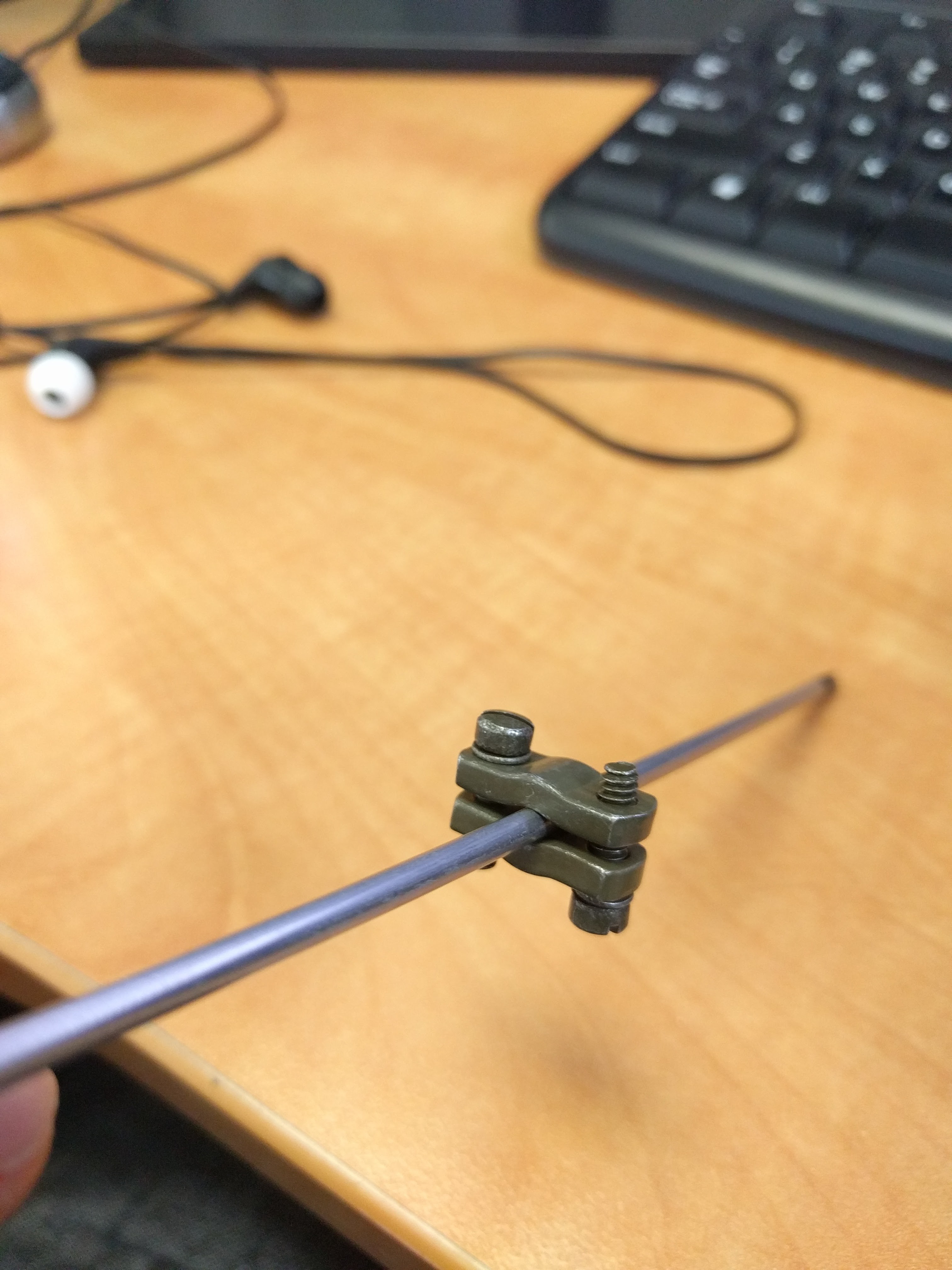
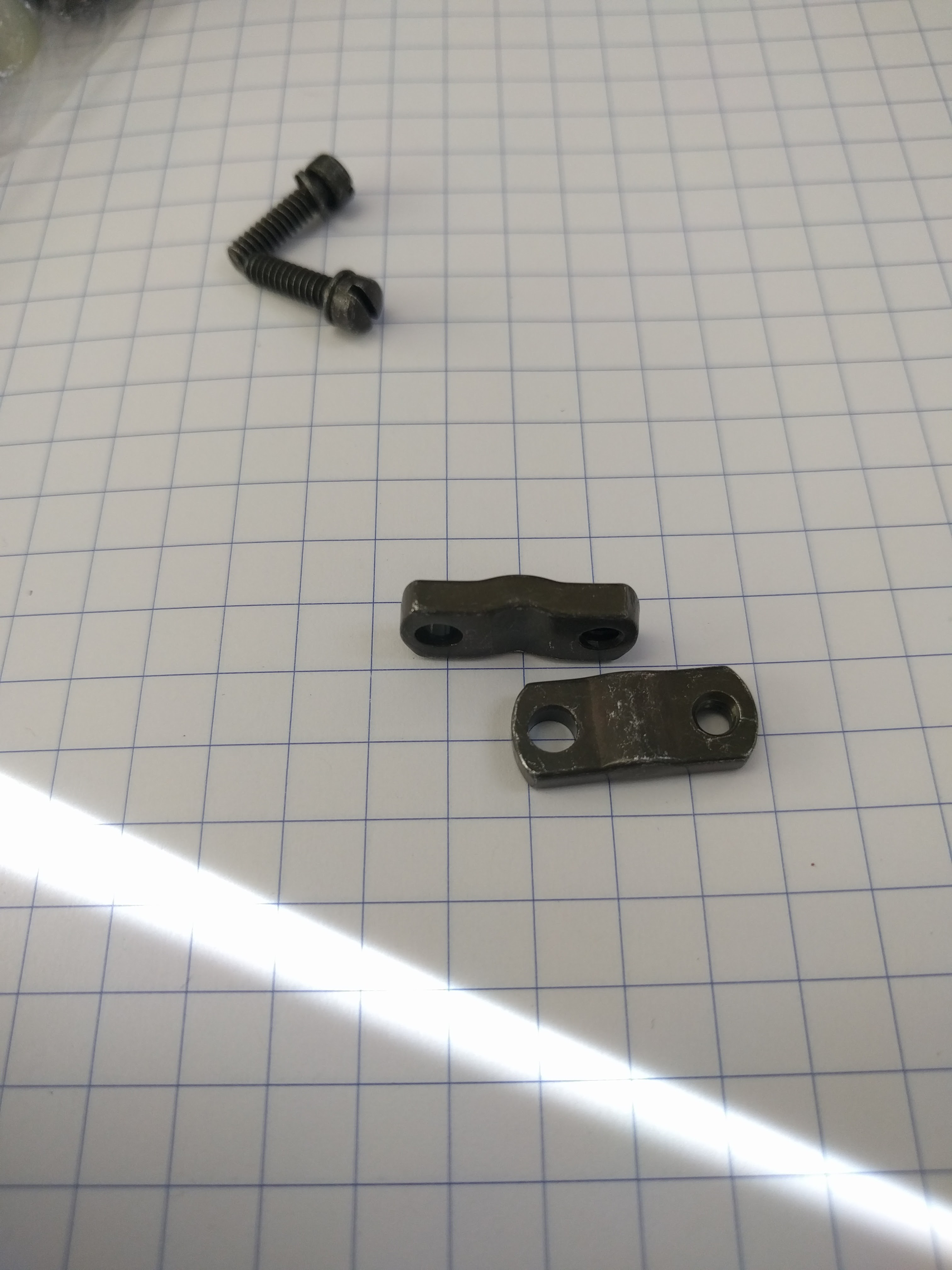
These are two identical plates, clearance holes on one side, and threaded holes on the other.
I don't know where to get them, or what they're called. Colour doesn't matter, but shape is important. These ones, and others I have seen, come as cable clamps for some DB15-style connectors.
Because they're just support pieces for connectors, however, they don't seem to be able to be purchased individually, or have dimensions associated with them. $4 for the entire package is cost prohibitive, too.
Another possible method:
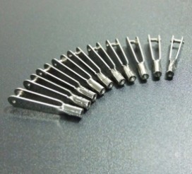
Hobby RC plane clevis pins.
There are a few issues with that, too.
There isn't really anything that fits both the shaft and the PCB thickness. They're cheaply made and inconsistently sized. They're also too long and eat up my vertical board space.
So what say you, internet? Any suggestions? Alternate ideas, or good sources for things?
Discussions
Become a Hackaday.io Member
Create an account to leave a comment. Already have an account? Log In.
Could you make the shafts out of brass and plate (or castellate) the inner sides of the slot? Then you could solder it. Brass solders nicely enough.
Are you sure? yes | no
That's definitely something for consideration!
Some issues I could see:
- Cheaper boardhouses can't do castellations or plated slots
- Rotational force might rip castellations right off the FR4
- I'm currently using 3mm precision rod. That plays really nicely with off-the-shelf shaft collars and bearings. A brass rod might be out of tolerance somewhat
- Might also be more prone to bending
I probably will try and do that on my PCB slots, though. I don't lose anything, and at the very least it could be an additional locking mechanism to another solution.
Are you sure? yes | no
yeah alignment, PCB fab expense, strength, etc are all concerns. I think in that case, an oversized slot for the axle and screw-on clamps of some kind are a decent idea. Could you get someone to weld some brackets onto your 3mm rod? That would help prevent slippage, since precision ground stuff can be pretty slippery..
Are you sure? yes | no
If I could find appropriate clamps, that'd be awesome!
My latest brainwave is D-profile shafts and lasercut wood or purchased FR4 shapes that mate them to the thin PCB. Simple enough that it never even occurred to me. It should work well, doesn't require a lot of of manual modification. Gonna order some parts to test it this evening.
Are you sure? yes | no