 Jarrett
Let's dive into how the code works, presently.
The main loop looks like this:
    while(1)
    {

        if (frame != angleInt && angleInt < HPIXELS) {
            frame = angleInt;

            DisableInterrupts();
            for(i = 0; i < VPIXELS; i++) {
                setChannel(blob, i, blueMap[frame][i]);
                setChannel(blob, 23 - i, greenMap[frame][i]);
            }
            LEDMap(blob);
            EnableInterrupts();

        }
    }
This is a little different than the final design, but the principle is similar. The testbench has one LED driver running two banks of 10 LEDs each. The final design will use 20 LEDs driven by two ICs. That should mean the main difference is that two LEDMap calls will be made.
Currently, the channel assignment code looks like this:
void setChannel(uint8_t *blob, uint8_t channel, uint16_t value) {
    uint8_t lvalue;
    uint8_t rvalue;
    uint8_t newVal;
    uint8_t byteAddr;

    if(channel % 2 == 0) {
        byteAddr = (channel * 3) >> 1;
        lvalue = (uint8_t)(value & 0xFF);
        rvalue = (uint8_t)(value >> 8);

        *(blob + byteAddr) = lvalue;
        newVal = (*(blob + byteAddr + 1)) & 0xF0;
        newVal = rvalue | newVal;

        *(blob + byteAddr + 1) = newVal;
    } else {
        byteAddr = (((channel - 1) * 3) >> 1) + 1;

        lvalue = (uint8_t)(value << 4) & 0xF0;
        rvalue = (uint8_t)(value >> 4);

        newVal = (*(blob + byteAddr)) & 0x0F;
        newVal = lvalue | newVal;

        *(blob + byteAddr) = newVal;
        *(blob + byteAddr + 1) = rvalue;
    }
}

void LEDMap(uint8_t *blob)
{
    uint8_t data = 0;

    XLAT = 0;

    for(int i = TABLESIZE - 1; i >= 0; i--) {
        data = *(blob + i);
        SPIWrite(data);
    }

    XLAT = 1;
    __delay_ms(10);
    XLAT = 0;
}
setChannel takes in a 16-bit value and address and puts it into a table of 12-bit values, using some magic that offsets everything into the proper address. The LED driver uses 12-bits for each channel, sent sequentially. There's a pretty glaring huge problem with this: It takes a ton of time to go through each row, many times per rotation. It has to be run for each pixel. In my final board, that will be 20 LEDs per driver, two drivers, and I'm hoping to get at least the same resolution on the vertical as horizontal (so 20 * Pi ~= 63 LED changes per rotation).
With a very rough test using AVR GCC with the Godbolt compiler (I know it's not the right architecture), we get:
~80 instructions * 24 channels * 2 banks = 3840 instructions for setChannel
~20 instructions * 36 channels * 2 banks = 1440 instructions for LEDMap
The PIC internal clock is 32MHz, but the instruction clock divides that by four:
8E6 / (3840 + 1440 instructions) = 1515 Hz for the entire loop.
Divide that again by 63 virtual horizontal pixels, and you get the full rotation of the PCB being maximum about 24 RPM. That's not nearly good enough!
The bulk of the processor time here is taken up by copying the currently active frame from input storage data into the output array, aligning it properly into 12-bit channels. What that means is that I can stick using 8-bit data and get more data out of my storage, at the cost of brightness resolution. We've discovered that it's also at the cost of unacceptable processor time, so I'll give the other method a shot, and try storing everything as a 36-byte table, representing 24 12-bit channels.
That brings us into a topic I've skipped talking about so far. The PIC family of microcontrollers is interesting because it is absolutely huge, with all kinds of different peripherals and weird combinations.
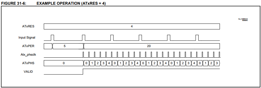
The one I've been using for testing, and likely the same (or similar) one I'll be using in the final model is the PIC16F1619. It is one of only 4 different models that have a poorly marketed and even more poorly documented Angular Timer. It's a fantastic peripheral, though, that does exactly what I need. You give it a periodic signal (eg. Hall Effect sensor triggered by a magnet), and it will divide that time up spit out an interrupt at regular intervals, depending on how many interrupts you want per period.
So that's taken a load off my code. After I set it up, the hardware just handles that portion for free.
Something that would be really nice, but probably isn't going to happen would be DMA. DMA peripherals are conspicuously absent from most of the 8-bit lines of Microchip's part selectors.
A little more digging however, turns up evidence that there is an SPI DMA peripheral in some of the newer PIC18FxxJxx families. As far as I can tell, it only mentioned in the datasheets of the affected products. Great marketing, Microchip!
None of those have the angular timer, however. I may do an analysis of the relative benefits of each peripheral at some point in the future, but for now, I'll stick with the PIC16F1619.
Discussions
Become a Hackaday.io Member
Create an account to leave a comment. Already have an account? Log In.