Close
0%
0%

Tactile Remote Control of a Mobile Device

Control your mobile device remotely without using the touch screen

Similar projects worth following
Distracted driving because of the use of cell phones causes thousands of deaths, and hundreds of thousands of injuries each year. Drivers take their eyes off the road to read a text or check navigation. Interacting with a phone is even more distracting, as the driver needs to focus completely on the phone in order to use the touch screen. It takes a fair bit of focus to look at a screen, determine what area you want to interact with, and move your finger to that exact location. Responding to texts, inputting new directions, making a call, and changing a song all take your eyes and focus off the road for several seconds at a time. In addition, ride sharing services rely on phone interaction for the driver to select their next fare, and to navigate to an unfamiliar area. It’s not likely that we can stop all drivers from being distracted by their phones, but it might be possible to lessen the distraction by providing a better way to interact touch screen devices while driving

Interacting with the touch screen while driving is far more distracting than just glancing at the phone to check a message.  The driver has to focus on a small section of the screen, and then focus to make sure there hand is in the right location before pressing down.  This sequence is then repeated multiple times, in the case of typing out a text message.  The act of sending even a short text message can take the driver’s focus of the road for many seconds at a time.  If the driver could interact with their phone without using the touchscreen, it would at least lessen the distraction and could end up saving lives. 

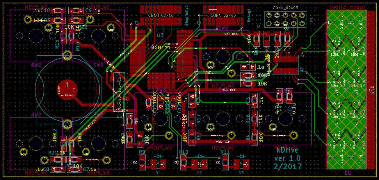
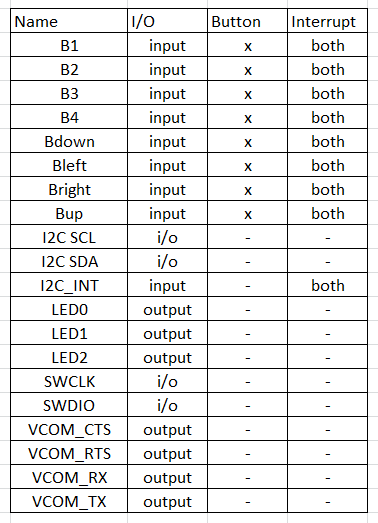
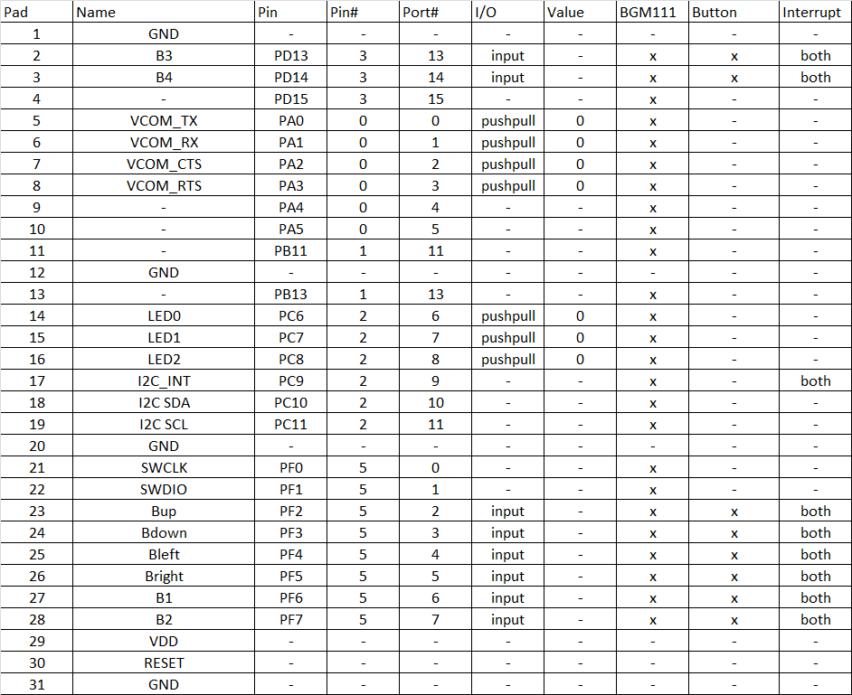
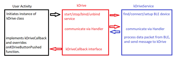
This product is a small keyboard like device that can be strapped to a steering wheel, or mounted somewhere else in the car the allows the driver to use tactile feedback to interact with their phone without looking at the screen.  The device has several buttons which can be distinguished by feel, which allow the driver to navigate through menus, activate voice control, and perform pre-programmed actions.  Android and Apple devices already provide support for using Bluetooth keyboards to navigate and provide input actions such as launching apps, filling out text forms, etc.  The device will also work with an application which lessens the distraction for common tasks such as texting, initiating phone calls, inputting navigation, selecting music, etc.  

It’s unfortunate that we can’t stop people from interacting with their phones while driving.  It is becoming more and more common as we become more reliant on our phones.  Many people the drive for ride sharing services even rely on the interaction to pick up a fare.  The goal of this product is to alleviate the distraction that is cause by interacting with cell phones while driving.  A few seconds of distraction is all it takes to cause an accident or to not recognize potential danger.  If we can keep the driver’s focus on the road, it can save thousands of lives every year.

Portable Network Graphics (PNG) - 149.08 kB - 10/26/2017 at 05:52

Preview
Download

Adobe Portable Document Format - 63.37 kB - 10/21/2017 at 06:28

Preview
Download

gbr - 61.04 kB - 10/21/2017 at 05:31

Download

gbr - 462.47 kB - 10/21/2017 at 05:31

Download

gbr - 103.20 kB - 10/21/2017 at 05:31

Download

View all 12 files

  • 1 × BGM111 Cortex M4 with BLE module
  • 1 × CPT112 Capacitive Touch Controller
  • 8 × Cherry MX1A Mechanical push buttons

  • Example App Flow

    Kyle Thomas10/26/2017 at 06:05 0 comments

    Here is an example app flow to show some of the potential actions of the kDrive.  The example here is thought out to keep minimal eyes on the device.  For example you can scroll through texts but pressing a button will initiate a read-back of the text. Similarly, to respond to text you could use the voice input instead of typing in letters.  Navigating to a location on a map can also be input via voice commands, or by pressing a button that is pre-programmed to navigate to a specific location.  All activities have one the same button programmed to take you back to the main screen.  These are just some examples of what can be done, but the buttons can be programmed to do a lot more!

  • Demo Videos

    Kyle Thomas10/21/2017 at 05:55 0 comments

    Here are three short videos describing the applications of the device, overviewing the components of the device, and a demo of the device in action controlling a cell phone.

  • CPT112 programming

    Kyle Thomas10/18/2017 at 05:36 1 comment

    The capacitive touch slider deserves a log all to itself.  I've never used one before, but i added the parts to the board anyways in hopes that it would work.  The CPT112 communicates over I2C which i am familiar with, so i figured i could get it working.

    The device can be set up to control 12 buttons, or one touch slider.  When an action is detected, the I2C interrupt pin is pulled low.  This is connected as an input to the micro-controller, which has an interrupt set up on that pin.  When the MCU detects a high->low transition, it knows that the CPT112 has some data to send, so it initiates a read.

    The data packet for the slider is a 4 byte value which includes a counter, and event code, an LSB and an MSB for the sider position.  So you have to I2C read 4 bytes, and then decode the packet in firmware.

    You program the settings of the touch controller using a silicon labs debug adapter and the Simplicity Studio IDE.  The settings you need depend on the layout of the touch slider, so there isn't exactly ideal settings that you just set an forget.  It took a bit of trial and error to get it to settings that felt smooth.

    There were a few gotcha's along the way that took some debugging to figure out.  

    • At first when i was playing around with the settings, I had the MCU communicating with the CPT112, and also had the debug adapter plugged in for programming and debugging using the DIE.  This was a problem because of the interrupt driven nature of the device.  When motion is detected, the interrupt pin is driven low, which flags the MCU to read the packet.  WIth the debug adapter plugged in, the debug adapter also tried to read the packet, so it became a race.   The packet reads are destructive, so it can only be read once.  I wasn't getting good performance in my application, and I wasn't getting good data through the Silicon Labs IDE.  So to optimize the settings, I disabled the MCU firmware, and used the Simplicity Studio IDE to get the settings correct.  Then i disconnected the debug adapter, and enabled my firmware to test it out in the application.
    • BLE offers two ways to communicate with a client (the mobile device),  Notifications and Indications.  When using indications, the client acknowledges back to the BLE device that data was received.  When using notifications, there is no acknowledgment.  Thus, notifications are much faster.  I had been using indications for all of my data transfer, such as when a button is pressed, the push buttons don't need fast data transfer.  The touch slider however, does need fast data transfer.  If you move your finger along the slider, it creates events at a very fast rate, as fast as every few ms.  This rate is too fast to use indications.  I realized that there was a bottleneck when using indications, so i had to change the data transfer method to notifications.
    • There is also a potential bottleneck in the BLE connection interval.  As stated before, i had set it to a fairly slow speed (every 50ms or so).  This was fast enough to process button presses.  This isn't fast enough to process the touch slider however, so i had to change the connection interval to the minimum (7.5ms).  This was mentioned in my 'to-do list' log.  This fast connection interval is only needed when the touch slider is being touched, and can be changed back to 50ms when it is not being touched to save power.

    Now that I had the CPT112 settings configured, and it communicating properly and quickly with the BGM111, i had to decide on what data to send back to the mobile device.  I wanted the MCU to do most of the processing, again for speed reasons.  The CPT112 only tells you the position of where your finger is on the slider (a number between 0 and 100).  So it is up to the firmware to process numerous reads into relevant information.  I figured...

    Read more »

  • Project Status

    Kyle Thomas10/13/2017 at 01:31 0 comments

    The previous logs are descriptions of the different parts of the project, but I haven't really commented on how well it works! As of right now, the device works but there is a lot of work left to get it working well, and with a fully functional android app.  I am an IC designer by trade, with some experience in embedded systems, but I've had to learn a lot about MCUs, firmwares, and android programming to get to this point.  I've focused mainly on getting the hardware working, with the intention on working on the app later or getting other people to work on it with me.  So this log is a kind of to-do list, some things i want to work on in the future now that I have the foundation of the device working properly.

    TO DO LIST!

    • FIRMWARE
      • The firmware processes short clicks, long clicks, and the capacitive touch slider.  I want to add the ability for double clicks, click-and-hold, multi-button clicks, rocker gestures....As mentioned before, i'd like to do this all in firmware because the MCU has better dection and timing control that would be needed to do a lot of this.
      • Power management: I haven't optimized the firmware for minimal power consumption.  Things that can be done are utilizing power down features of the MCU, optimizing the BLE settings, blinking the LEDS instead of leaving them on full time...For example as i will discuss in a later log, i had to make the BLE connection interval very fast in order to get the capacitive touch slider working decently.  This is only needed when the capacitive touch slider is being touched however.  If its not being touched, I can slow the BLE connection interval down, which saves power.
    • HARDWARE
      • The PCB board worked in its first rev, although not without a little bit of modifications.  For starters, none of my headers were correct.  Lesson learned, the kicad footprint wizard defaults to pin numbers that 'zig zag'.  IE, in a DIP socket, pin 1 is across from pin 2..pin 3 is across from  pin 4, etc.c  Every package ive ever used starts with pin 1 in the upper left, and goes around the package counter clockwise.  So i had to create custom cables just to hook the thing up, it was a real pain!
      • I also flipped the connections to the coin cell battery socket, whoops :)
      • I could never get the AEM monitor to work.  The board has 3 powering options.  VDD from the development board, VDD from the coin cell, or VDD through the development boards "AEM".  This allows you to use the silicon libraries IDE to monitor power consumption in real time.  Seems like a neat feature, i couldn't get it to work, so i need to double check those connections.
      • I layed out the capacitive touch slider using the kiCad footprint wizard as well.  Its a cool feature, but i think my slider can use some layout improvements.  If you drag your finger slowly across it, you can notice some 'dead spots' where the values don't change.
    • ANDROID APP
      • Lots do do here.  Each activity needs to implement the callback functions, to do anything.  Ideally there would be a default action for each button that would be pretty generic (ie implement keypad_up), then you could override those functions if you wanted it to do something different.  
      • I need to do more research on HID, and inter-application communication.  I wanted to do all the communications in a service so that it could run in the background, and be able to be used in any app.  I'm not sure if this is possible.  Having the device act as an HID might make this possible, but i haven't learned how to do that.
      • I only have two activities right now.  A list that shows all my contacts that you can scroll through, and a map that you can pan left/right/up/down.  Theres tons of development that could be done with the device, including a music player, text viewer, etc.  If I can't get HID or inter-app working, then i'll have to rely on my own app to handle anything...
    Read more »

  • PCB Layout

    Kyle Thomas10/10/2017 at 05:59 2 comments

    PCB LAYOUT

    I want the device to be about the size of a cell phone or smaller, so that it can be strapped to a steering wheel or mounted somewhere in the car.  The buttons alone take up quite a bit of space, so I decided to put all of the components on the top of the device, and all of the buttons on the bottom.  The blue rectangle is the capacitive touch slider, and the purple squares are the push buttons.  The four on the left will be used for navigation purposes (up/down/left/right).  The four buttons on the right are general purpose buttons that can be used for whatever the developer wants to do.

    All of the components are on the top side of the board.  In addition to the components listed in previous logs, I also added a manual switch to control power to the board.  The three way switch lets you select whether you want power to come from the battery, from the development board, or using the development board’s power monitor system.  This lets you monitor the power consumption in real time using the Silicon Labs IDE.  The final BGM111 pinout was also selected to try and make the PCB layout easier, such as grouping the I2C pins together at the bottom of the package.  I tried to make the footprint of the BGM111 big enough so that I could hand solder it to the board.  At the top of the board you can see three headers, two for the BGM111 development board, and one for the CPT112 programming toolkit.

  • CPT112 - capacitive touch controller from Silicon Labs

    Kyle Thomas10/07/2017 at 16:12 0 comments

    CPT112

    The CPT112 touch processor can support up to 12 capacitive touch buttons, but can also be used to support a single capacitive touch slider, which is how it will be used in this application. 

    The touch slider was layed out using the kiCad footprint wizard, which can automatically generate capacitive touch sliders.  The slider on this board is 5 segments. 

    The CPT112 needs the following connections:

    CS01-CS05:  Connections to each of the 5 capacitive touch segments.

    CNFG_CLK, CNFG_DATA:  Connects to the programming header

    I2C_INT, I2C_DATA, I2C_SCL:  Connects to BGM111 with use of pullup resistors.

    This part of the project will have its own log post later, describing the progamming and firmware required to support the chip.  The chip itself is pretty easy to use since it is I2C capable, but getting the capacitive slider to work the way i wanted took a fair bit of time!

  • Push Buttons and LEDs

    Kyle Thomas10/07/2017 at 16:08 0 comments

    PUSH BUTTONS
    I wanted nice feeling buttons for the device, so I looked at the Cherry MX series of buttons.  They are mechanical buttons and have several different options for height/weight and press action.  I sampled a few different types and ultimately decided on Chery MX1A-C1NW buttons.  The only circuitry needed to support the buttons is debouncing circuitry.  The buttons are open circuit when not pressed, and closed circuit when pressed.  
    The debouncing circuit is necessary to provide glitch free transitions when a button is pressed or released.  The RC circuits slow down the rise and fall times so that only one transition is detected for each button press.   
     
    LEDs
    I chose a red, green, and blue LED for general purpose.  As of right now, I’m just using the red LED to determine if the board has power.  The blue LED is controlled by the firmware, and turns on when the BLE device is connected.  It turns off when the BLE device is disconnected.

  • BGM111 - BLE Module from Silicon Labs

    Kyle Thomas10/07/2017 at 16:07 0 comments

    With all of the components defined, we need to map out the GPIO for the BGM111.  I have 8 push buttons, 3 LEDs, and one capacitive touch processor that communicates using I2C.  I also want the UART pins available so that I can use the debugging functions of the BMG111.  

    The BGM111 has 25 GPIO pins that can be used.  The pins are organized into 5 ports, so we have:
    Port A:  PA0, PA1, PA2, PA3, PA4, PA5
    Port B:  PB11, PB13
    Port C:  PC6, PC7, PC8, PC9, PC10, PC11
    Port D:  PD13, PD14, PD15
    Port F:  PF0, PF1, PF2, PF3, PF4, PF5, PF6, PF6
    Any of the pins can be used as interrupts; however, the interrupts are determined by the Pin number only.  For example, if you set an interrupt on PF4, it will also be triggered if there is a detection of an interrupt on PA4 as well.  The 8 push buttons will be set as inputs and need interrupts.  The I2C_INT pin is also an input that needs an interrupt.  I don’t want any of these pins to trigger interrupts on each other, so I need to arrange the pinout in specific manner.

    UART:  By default, the BGM111 uses PA0, PA1, PA2, PA3 for UART.  This can be changed but we’ll start with this and see if we can fit the other GPIOs.

    Push Buttons: All 8 of these pins need unique pin numbers for them to work with interrupts.  I’ll use PF2-PF7, and PD13-PD14.  I’ll set them as inputs and set the interrupts to trigger on the rising and falling edge, because I want to be notified when the button is pressed and when the button is released.  This is essential to process whether it is a short click or a long click.

    I2C:  We need to also set an interrupt on the I2C_INT pin for the CPT112.  This is used to tell us when the CPT112 has data it wishes to send over I2C.  pins 2-7, and 13-14 are used already used for interrupts, so I’ll use PC9 for I2C_INT.  I can then use PC10 and PC11 for I2C_SDA, and I2C_SCL. 

    LEDs:  The LEDs are just used as push/pull outputs.  They do not need interrupts.  The GPIO can drive 20mA of current so that should be enough to drive an LED.  I’ll use PC6, PC7, PC8 to drive the LEDs.  The pins will source current, so a logic HIGH on the pin will turn the LED on. 

    SWDIO/SWCLK:  These are the programming pins for the BGM111.  We can use pins PF0 and PF1.

    Heres the final pinout for the BGM111

  • Hardware Prototype

    Kyle Thomas10/07/2017 at 16:05 0 comments

    Up until now I’ve been using the Silicon Labs development board and a hand wired breadboard with a few buttons.  This was enough to develop the beginning of the firmware and android.  The next step is to build a PCB prototype of the device that can be used independently of the development board.  The list of the board components is as follows:

    • BGM111 MCU
    • 3 LEDs – for visual indications, such as when the mobile device connects to the kDrive.
    • 8 Tactile push buttons
    • Reistors/Capacitors for debouncing the push buttons
    • CPT112 capacitive touch processor
    • Layout for capacitive touch slider
    • Header to program the CPT112
    • C2032 Cell battery socket
    • Headers to connect to development board.  The development board is still used to program the MCU and for debug purposes.

    I’ll go into the details of each component in their own log post.

  • Initial Prototype

    Kyle Thomas10/06/2017 at 01:04 0 comments

    The initial prototype as done using just the BGM111 development board and a small hand soldered breadboard containing a few push buttons.  The bulk of the work in this stage is getting the firmware of the BGM111 to communicate with the basic android app.  Once a few buttons were working properly we could expand the firmware to accommodate more buttons.  Many of the core design choices were made at this stage.  Some of the design choices are:

    • Process clicks in hardware or software
      • I want the user to be able to interact with a button in multiple ways, just like a keyboard or touch screen.  This includes single clicks, long clicks, multiple clicks, simultaneous clicks, and holding down a button.  Processing all the types of click can either be done inside the Android app or inside the firmware of the MCU.  I chose to do all of this in the MCU.  The processor is more than equipped to handle it, and it take some load off the phone as well as limits the amount of data  need to transfer of BLE.  The MCU also has a more precise clock that is used to determine long clicks.  As of right now, only single clicks and long clicks are implemented.
      • The GPIOs are setup to interrupt on the rising and falling edge, so that we know when a button is pressed and when it is released.  When a button is pressed, the MCU starts a timer.  When that button is released, it checks the status of the timer.  If the elapsed time is more than one second, then a long click is processed.  If the time is less than one second, then a short click is processed.
    • What data to send over Bluetooth
      • We need to send a packet of data from the MCU to the android app.  For the buttons, the packet is quite simple.  One byte for the button ID, and one byte for the type of click processed.  
    • Outline of GATT profile
      • The GATT profile includes a service, and this service includes several characteristics, 2 bytes each.   Each characteristic corresponds to one button.  After a button is processed in the firmware, we will write a value to the characteristic corresponding to the pressed button, and then issue a BLE notification which alerts the android app that something has changed.  
    • Bluetooth connection settings
      • The BLE connection settings do not need to be high speed.  We are just processing user interaction, which is fairly slow.  A user probably can’t push a button more than 10 times per second or so.  We can set the connection interval to 50ms for now to save power.  
    • Android app flow
      • When initiated, the android app goes through the following actions to set up the BLE connection:
      • onLeScan callback is called, searches broadcasted devices found for name “kDrive”.  Attemps to connect, if found
      • If successful, attempt to discover GATT services
      • If services discovered, enable GATT notifications
      • Once notifications are enabled, the setup is complete.  
      • The service then waits for the onCharacteristicChanged function to fire, which happens when the Bluetooth device sends a notification or indication.  The android app then processes the packet of data, unpacking the button ID and click type.  
      • The service now needs to send a message back to the kDrive class so that the current activity can act on it.  The service sends a bundle of data to the kDrive class.  
      • The kDrive class receives a message from the kDriveService, and initiates a callback function.  The callback function is overridden in the current activity, so that each activity can act upon the button however it pleases.

View all 13 project logs

Enjoy this project?

Share

Discussions

Similar Projects

Does this project spark your interest?

Become a member to follow this project and never miss any updates