 Kyle Thomas
With all of the components defined, we need to map out the GPIO for the BGM111. I have 8 push buttons, 3 LEDs, and one capacitive touch processor that communicates using I2C. I also want the UART pins available so that I can use the debugging functions of the BMG111.
The BGM111 has 25 GPIO pins that can be used. The pins are organized into 5 ports, so we have:
Port A: PA0, PA1, PA2, PA3, PA4, PA5
Port B: PB11, PB13
Port C: PC6, PC7, PC8, PC9, PC10, PC11
Port D: PD13, PD14, PD15
Port F: PF0, PF1, PF2, PF3, PF4, PF5, PF6, PF6
Any of the pins can be used as interrupts; however, the interrupts are determined by the Pin number only. For example, if you set an interrupt on PF4, it will also be triggered if there is a detection of an interrupt on PA4 as well. The 8 push buttons will be set as inputs and need interrupts. The I2C_INT pin is also an input that needs an interrupt. I don’t want any of these pins to trigger interrupts on each other, so I need to arrange the pinout in specific manner.
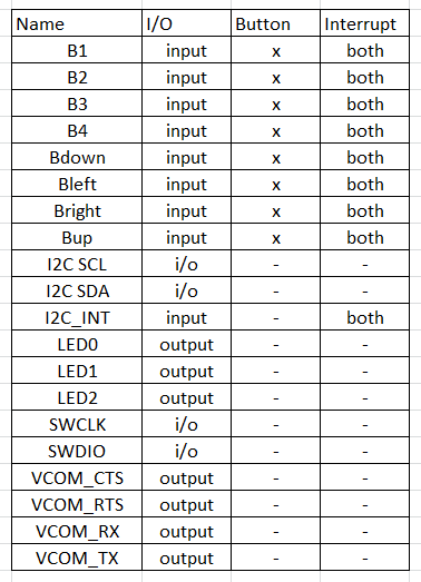
UART: By default, the BGM111 uses PA0, PA1, PA2, PA3 for UART. This can be changed but we’ll start with this and see if we can fit the other GPIOs.
Push Buttons: All 8 of these pins need unique pin numbers for them to work with interrupts. I’ll use PF2-PF7, and PD13-PD14. I’ll set them as inputs and set the interrupts to trigger on the rising and falling edge, because I want to be notified when the button is pressed and when the button is released. This is essential to process whether it is a short click or a long click.
I2C: We need to also set an interrupt on the I2C_INT pin for the CPT112. This is used to tell us when the CPT112 has data it wishes to send over I2C. pins 2-7, and 13-14 are used already used for interrupts, so I’ll use PC9 for I2C_INT. I can then use PC10 and PC11 for I2C_SDA, and I2C_SCL.
LEDs: The LEDs are just used as push/pull outputs. They do not need interrupts. The GPIO can drive 20mA of current so that should be enough to drive an LED. I’ll use PC6, PC7, PC8 to drive the LEDs. The pins will source current, so a logic HIGH on the pin will turn the LED on.
SWDIO/SWCLK: These are the programming pins for the BGM111. We can use pins PF0 and PF1.
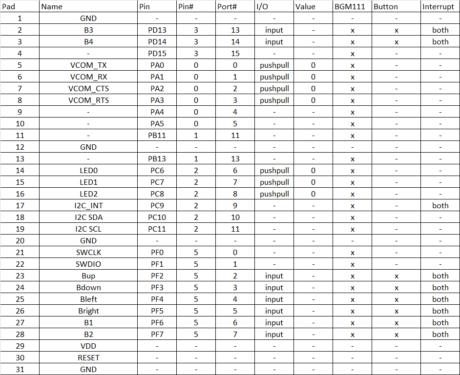
Heres the final pinout for the BGM111
Discussions
Become a Hackaday.io Member
Create an account to leave a comment. Already have an account? Log In.