 David Scholten
The PCB is powered by a 3 cell Lithium Polymer battery (standard hobby chemistry), which has a maximum voltage of 12.6V and safe minimum of 9.9V. All of the modules and systems (except for the 3.3V IMU) will gladly accept an operating voltage of 5V. However, all the systems that have been selected actually communicate with 3.3V logic (go figure). As a result, the µcontroller must be powered from a 3.3V supply to allow successful integration. To satisfy these requirements, a step-down switching regulator is used to produce the 5V supply (which may see loads of up to 1A), which is then fed into a low-dropout linear regulator to produce the 3.3V supply (that has only light loads <15mA). In this way efficiency and complexity are optimised.
Linear 3.3V Regulator
Surprisingly, the Seeed library of parts does not contain many fixed-output 3.3V linear regulators. As a result the regulator selected (LP2985) has the added complexity of an extra two pins for futher functionality (which of course is unused).
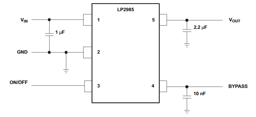
There are some requirements for the output capacitance Equivalent Series Resistance (ESR) to fall within a specified ranges, but almost any ceramic X7R capacitor will do the trick. The design is simple enough and can be seen below:
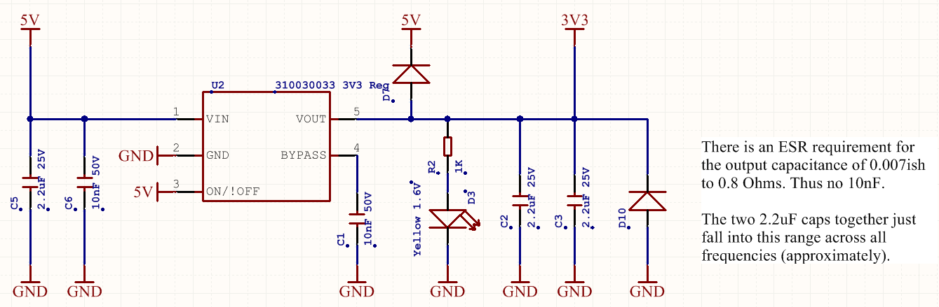
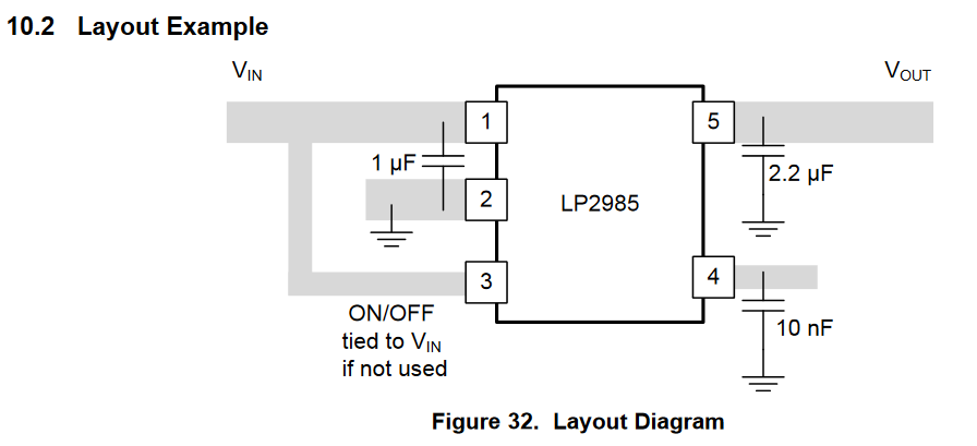
The datasheet was even kind enough to offer layout advice, but it’s hardly worth it for a linear regulator.
Switching Step-Down 5V (5.1V) Regulator
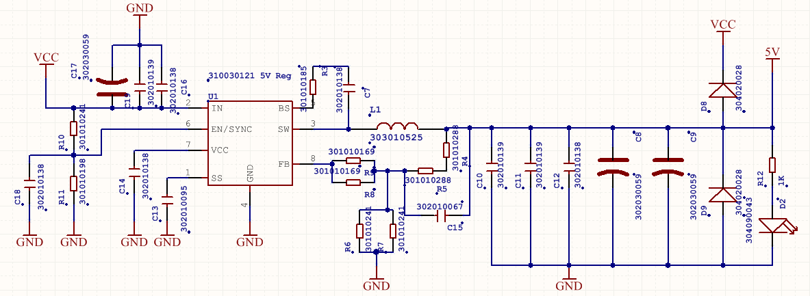
For the primary power conversion stage that takes care of regulating the battery to 5V, the MP1496 switching regulator was used. This chip is far more involved than the 3.3V linear regulator, but a whole lot more powerful! Below we can see a typical application (for 3.3V):
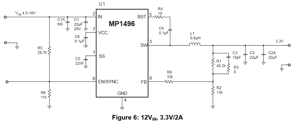
The only pins that are important here are 3, 5 & 8, which all relate to the output and its behaviour.
- Pin 5: The bootstrap pin, which allows for high side switching of the internal transistor. This ultimately allows for a common ground between the input and load.
- Pin 8: The feedback pin, which allows the output regulation voltage to be set. For our case it was set to about 5.1V
- Pin 3: The 500kHz switching voltage to be fed to the output filter.
To select the output inductor, the following formula was followed according to the datasheet:
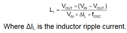
The inductor value selected (22µH @ about 2A) for the worst case scenario is a little too low due to Seeed library constraints, which just means the output capacitor had to be sized a little higher (2µF ceramic) according to the 'low ESR approximation formula':

Which gives a voltage ripple of 34mV, but an additional electrolytic cap ought to help smooth this out. Seen below is the Altium implementation:
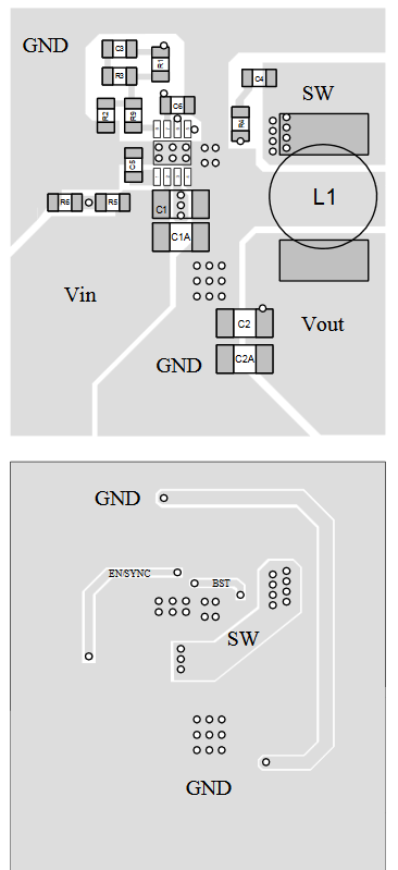
For the actual PCB layout (not yet started), the following datasheet guide will prove very useful in ensuring the correct operation of the device at the 500kHz switching frequency and assist with the positioning of the bypass capacitors, etc. to reduce noise, transmissions, mutual inductance and general high frequency impedance:
Power Protection Capability
To protect the PCB from damage or unexpected failures, the following input circuit is used:
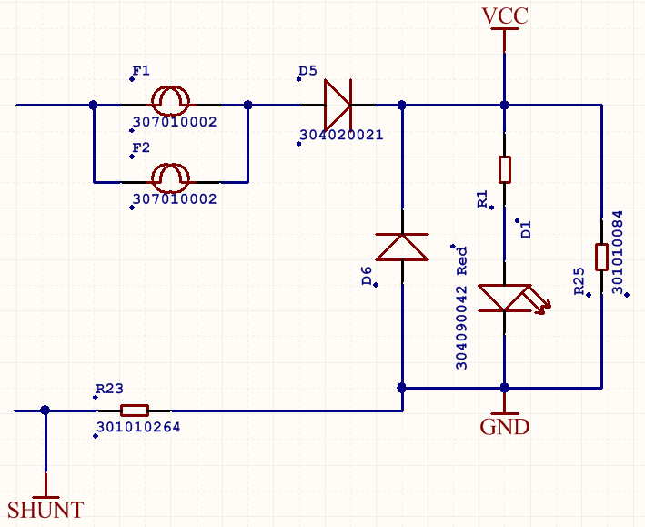
A fuse protects from flame/smoke hazards in the event of a short and two diodes are used to provide reverse polarity protection. D5 blocks the reverse voltage whilst D6 ensures that (in the reverse condition) the impedance of the load is low enough so as to experience a maximum reverse voltage of about 0.5V. Additionally, this input is also connected directly to the 5V and 3.3V rails via a reverse biased low-drop diode (seen in the 5V (D8) and 3.3V (D7) regulator Altium screen shots). These diodes allow energy to flow from those rails to the input in the event that the battery is removed, which avoids reverse biasing the 5V and 3.3V regulators. Without this they may fail on the first power down.
Coming up next: µcontroller implementation!
Discussions
Become a Hackaday.io Member
Create an account to leave a comment. Already have an account? Log In.