 David Scholten
Each Pedal Prix race has a running time of at least 6 hours, which is demanding on the capacity of the battery (that has already been minimised in size to reduce weight). As such, it is almost guaranteed that the battery needs to be replaced at least once during the race. To maximise the usage of each battery it is highly desirable to know the remaining electrical energy at all times during the race. This therefore requires both voltage and current measurement capability on the PCB.
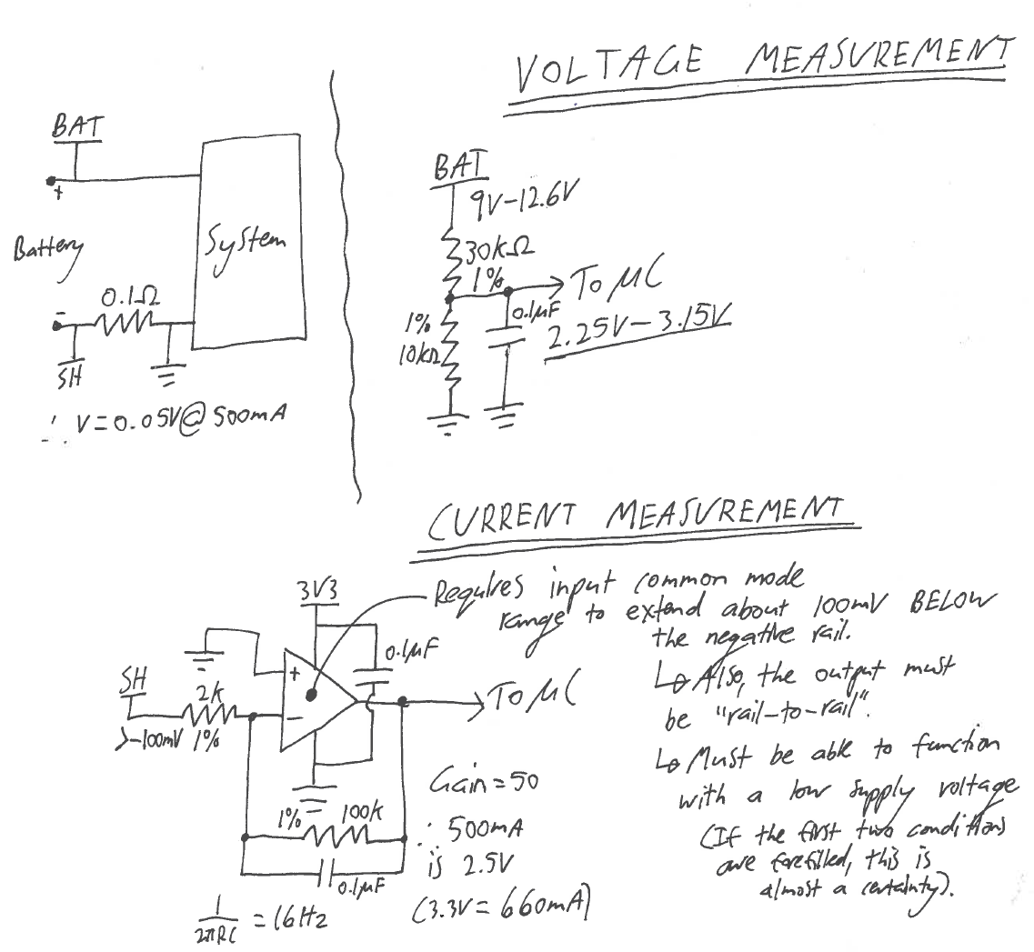
Voltage Measurement:
Voltage measurement of the battery is very simple, consisting of a resistive divider and a filtering capacitor. So long as the divider resistance is low compared to the µcontroller input, no current buffer is required. As the battery voltage is “stiff” (i.e. no sag under the expected current draw), the voltage does change transiently. Thus, there is no AC component to the voltage source (battery) and the measured signal can be heavily filtered. Filtering cannot be used when both the source voltage and load current contain AC components (potential for phase differences and a power factor below 1).
Current Measurement:
Thus, as the source voltage is effectively pure DC, the measured current signal can also be heavily filtered as the power measurement is now simply the battery voltage multiplied by the average current. However, the current is technically more complex to measure due to shunt requirements.
A shunt on the positive side of the battery terminals requires a differential amplifier to condition the signal to have a zero point at ground. However, the voltage must be first divided down to protect the Op-Amp that is powered by only a 3.3V rail. This in turn reduces the differential Op-Amp voltage output and increases the gain requirement of a subsequent cascaded Op-Amp stage.
To correct this over-voltage problem, a shunt is instead used on the return side of the battery. Seen in the image, the 0.1Ohm shunt produces a small voltage that is negative with respect to the rest of the system (Op-Amp included). The Op-Amp chosen for this role should have:
- A common mode range that extends beyond the rails (i.e. about Vee-0.1V to Vcc+0.1V).
- Rail-to-Rail operation at the output to allow for a true zero-voltage output for an asymmetrical power supply (i.e. no negative rail available).
- The ability to function with a small supply voltage (3.3V rail).
So long as the Op-Amp can achieve these goals (OPA333AIDBVT was chosen) we can simply use an inverting Op-Amp configuration that allows gain relative to the true ground zero-point, but inverts the signal. Effectively, the non-inverting amplifier is a differential amplifier anyway (0V minus the negative signal), so the inversion comes naturally. As an added bonus, low pass filtering can be simply integrated with a single capacitor in parallel with R2 (infinite roll off!). The equation for the entire system at steady state is (i.e. DC component only):
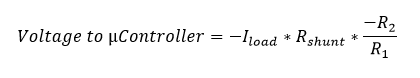 Where the maximum voltage of 3.3V represents 660mA for the µcontroller in the presented system. It is important to note that the exact resistance of the shunt needs to be known.
Finally, here is the Altium 2017 implementation:
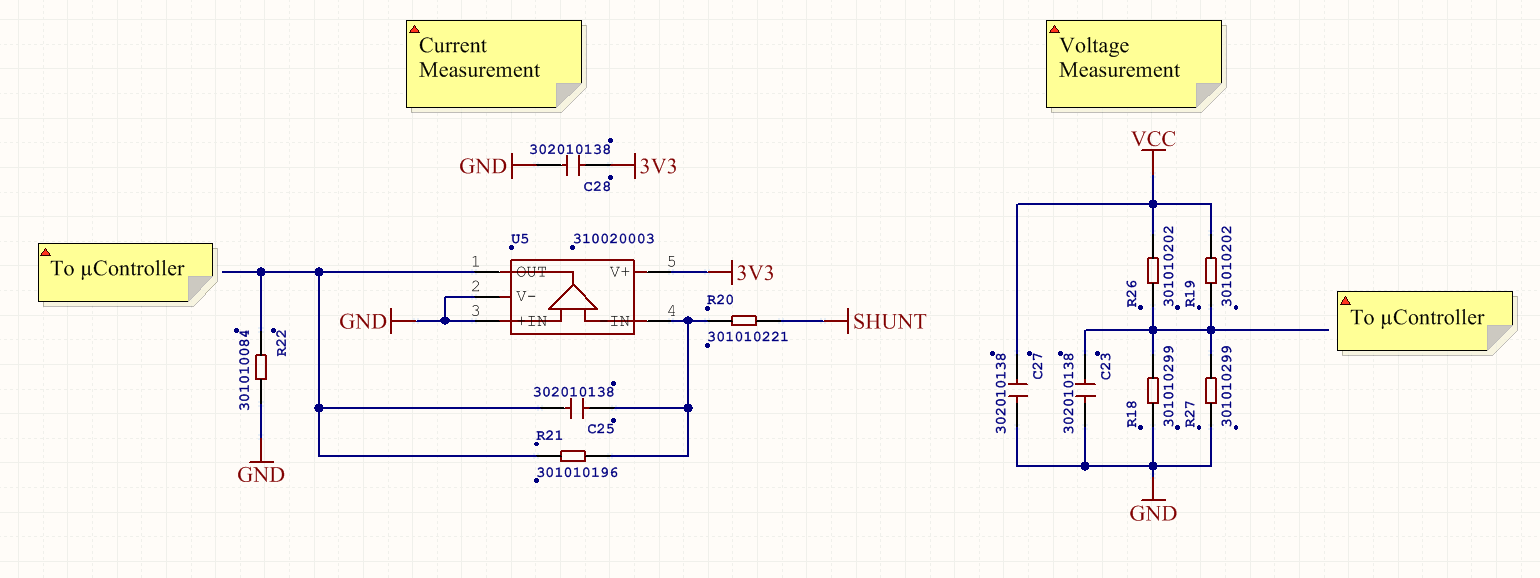
In the end it's nothing more than a basic Op-Amp implementation, but it was fun none-the-less!
Discussions
Become a Hackaday.io Member
Create an account to leave a comment. Already have an account? Log In.